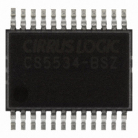
CS5534-BSZ Cirrus Logic Inc, CS5534-BSZ Datasheet - Page 35

CS5534-BSZ
Manufacturer Part Number
CS5534-BSZ
Description
IC ADC 24BIT 4CH W/LNA 20SSOP
Manufacturer
Cirrus Logic Inc
Specifications of CS5534-BSZ
Number Of Converters
1
Package / Case
24-SSOP
Number Of Bits
24
Sampling Rate (per Second)
3.84k
Data Interface
Serial
Power Dissipation (max)
45mW
Voltage Supply Source
Analog and Digital, Dual ±
Operating Temperature
-40°C ~ 85°C
Mounting Type
Surface Mount
Number Of Adc Inputs
4
Architecture
Delta-Sigma
Conversion Rate
6.25 SPs to 3840 SPs
Resolution
24 bit
Input Type
Voltage
Interface Type
Serial (3-Wire)
Voltage Reference
2.5 V
Maximum Power Dissipation
500 mW
Maximum Operating Temperature
+ 85 C
Mounting Style
SMD/SMT
Minimum Operating Temperature
- 40 C
Lead Free Status / RoHS Status
Lead free / RoHS Compliant
For Use With
598-1016 - EVAL BOARD FOR CS5534
Lead Free Status / Rohs Status
Lead free / RoHS Compliant
Other names
598-1116-5
Available stocks
Company
Part Number
Manufacturer
Quantity
Price
Company:
Part Number:
CS5534-BSZ
Manufacturer:
Qorvo
Quantity:
10
Company:
Part Number:
CS5534-BSZ
Manufacturer:
CIRRUS
Quantity:
676
Part Number:
CS5534-BSZ
Manufacturer:
CIRRUS
Quantity:
20 000
2.6.3. Examples of Using CSRs to Perform
Conversions and Calibrations
Any time a calibration or conversion command is
issued (C, MC, and CC2-CC0 bits must be properly
set), the CSRP2-CSRP0 bits in the command byte
are used as pointers to address one of the Setups in
the channel-setup registers (CSRs). Table 3 details
the address decoding of the pointer the bits.
DS289F5
FRS (WR3-WR0)
(CSRP2-CSRP0) CSR Location
0
0
0
0
0
0
0
0
0
0
1
1
1
1
1
1
1
1
1
1
Table 2. Conversion Timing – Continuous Mode
000
001
010
011
100
101
110
111
0000
0001
0010
0100
1000
1001
1010
0000
0001
0010
0100
1000
1001
1010
0011
1011
1100
0011
1011
1100
Table 3. Command Byte Pointer
(First Conversion)
Clock Cycles
1581994 ± 10
1318328 ± 8
107434 ± 10
205738 ± 10
402346 ± 10
795562 ± 10
CSR #1
CSR #1
CSR #2
CSR #2
CSR #3
CSR #3
CSR #4
171448 ± 8
335288 ± 8
662968 ± 8
15274 ± 10
21418 ± 10
33706 ± 10
58282 ± 10
CSR#4
89528 ± 8
12728 ± 8
17848 ± 8
28088 ± 8
48568 ± 8
2966 ± 10
2472 ± 8
Conversions)
Clock Cycles
Setup
(All Other
163840
327680
655360
196608
393216
786432
40960
81920
10240
20480
49152
98304
12288
24576
1
2
3
4
5
6
7
8
1280
2560
5120
1536
3072
6144
The examples that follow detail situations that a
user might encounter when acquiring a conversion
or calibrating the converter. These examples as-
sume that the CSRs are programmed with the fol-
lowing physical channel order: 4, 1, 1, 2, 4, 3, 4, 4.
A physical channel is defined as the actual input
channel (AIN1 to AIN4) to which an external sig-
nal is connected.
Example 1: Single conversion using Setup 1. The
command issued is ‘10000000’. This instructs the
converter to perform a single conversion referenc-
ing Setup 1 (CSRP2 - CSRP0 = ‘000’) In this ex-
ample, Setup 1 points to physical channel 4. After
the command is received and decoded, the ADC
performs a conversion on physical channel 4 and
SDO falls to indicate that the conversion is com-
plete. To read the conversion, 40 SCLKs are then
required. Once the conversion data has been read,
the serial port returns to the command mode.
Example 2: Continuous conversions using Setup 3.
The command issued is ‘11010000’. This instructs
the converter to perform continuous conversions
referencing Setup 3 (CSRP2 - CSRP0 = ‘010’). In
this example, Setup 3 points to physical channel 1.
After the command is received and decoded, the
ADC performs a conversion on physical channel 1
and SDO falls to indicate that the conversion is
complete. The user now has three options. The user
can acquire the conversion and remain in this
mode, acquire the conversion and exit this mode, or
ignore the conversion and wait for a new conver-
sion at the next update interval, as detailed in the
continuous conversion section.
Example 3: Calibration using Setup 4. This exam-
ple assumes that the OGS bit in the Configuration
Register is set to ‘0’. The command issued is
‘10011001’. This instructs the converter to perform
a self offset calibration referencing Setup 4
(CSRP2 - CSRP0 = ‘011’). In this example, Setup
4 points to physical channel 2. After the command
is received and decoded, the ADC performs a self
CS5531/32/33/34-AS
35


