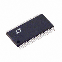
LTC1750IFW Linear Technology, LTC1750IFW Datasheet - Page 2

LTC1750IFW
Manufacturer Part Number
LTC1750IFW
Description
IC ADC 14BIT 80MSPS SMPL 48TSSOP
Manufacturer
Linear Technology
Datasheet
1.LTC1750CFW.pdf
(20 pages)
Specifications of LTC1750IFW
Number Of Bits
14
Sampling Rate (per Second)
80M
Data Interface
Parallel
Number Of Converters
1
Power Dissipation (max)
1.69W
Voltage Supply Source
Single Supply
Operating Temperature
-40°C ~ 85°C
Mounting Type
Surface Mount
Package / Case
48-TFSOP (0.240", 6.10mm Width)
Lead Free Status / RoHS Status
Contains lead / RoHS non-compliant
Available stocks
Company
Part Number
Manufacturer
Quantity
Price
Part Number:
LTC1750IFW#PBF
Manufacturer:
LINEAR/凌特
Quantity:
20 000
ABSOLUTE
CO VERTER CHARACTERISTICS
A ALOG I PUT
LTC1750
OV
Supply Voltage (V
Analog Input Voltage (Note 3) .... – 0.3V to (V
Digital Input Voltage (Note 4) ..... – 0.3V to (V
Digital Output Voltage ................. – 0.3V to (V
OGND Voltage ..............................................– 0.3V to 1V
Power Dissipation ............................................ 2000mW
Operating Temperature Range
Storage Temperature Range ................. – 65 C to 150 C
Lead Temperature (Soldering, 10 sec).................. 300 C
temperature range, otherwise specifications are at T
PARAMETER
Resolution (No Missing Codes)
Integral Linearity Error
Differential Linearity Error
Offset Error
Gain Error
Full-Scale Tempco
Offset Tempco
Input Referred Noise (Transition Noise)
specifications are at T
SYMBOL
V
I
C
t
t
t
CMRR
2
IN
ACQ
AP
JITTER
IN
IN
U
DD
LTC1750C ............................................... 0 C to 70 C
LTC1750I ............................................ – 40 C to 85 C
U
= V
DD
PARAMETER
Analog Input Range (Note 8)
Analog Input Leakage Current
Analog Input Capacitance
Sample-and-Hold Acquisition Time
Sample-and-Hold Acquisition Delay Time
Sample-and-Hold Acquisition Delay Time Jitter
Analog Input Common Mode Rejection Ratio
(Notes 1, 2)
U
DD
W
MAXIMUM
A
) ............................................. 5.5V
= 25 C. (Note 5)
W W
The
indicates specifications which apply over the full operating temperature range, otherwise
RATINGS
CONDITIONS
(Note 6)
(Note 7) External Reference (V
External Reference (V
Internal Reference
External Reference (V
V
SENSE
= 1.125V, PGA = 0
U
A
DD
DD
DD
= 25 C. (Note 5)
CONDITIONS
4.75V V
0 < A
Sample Mode ENC < ENC
Hold Mode ENC > ENC
1.5V < (A
+ 0.3V)
+ 0.3V)
+ 0.3V)
IN
The
SENSE
SENSE
+
, A
IN
DD
IN
–
= 1.125V, PGA = 0)
= 1.125V)
–
indicates specifications which apply over the full operating
= A
< V
SENSE
5.25V
PACKAGE/ORDER
Consult LTC Marketing for parts specified with wider operating temperature ranges.
IN
DD
+
) < 3V
MSBINV
= 1.125V, PGA = 0)
SENSE
REFHA
REFHB
REFLB
REFLA
GND
GND
GND
GND
GND
GND
GND
GND
V
A
A
ENC
ENC
V
V
V
V
V
IN
IN
CM
DD
DD
DD
DD
DD
+
–
10
11
12
13
14
15
16
17
18
19
20
21
22
23
24
1
2
3
4
5
6
7
8
9
T
JMAX
48-LEAD PLASTIC TSSOP
= 150 C,
FW PACKAGE
TOP VIEW
JA
= 35 C/W
MIN
–1
48
47
46
45
44
43
42
41
40
39
38
37
36
35
34
33
32
31
30
29
28
27
26
25
–3.5
MIN
–35
– 3
–1
14
OF
OGND
D13
D12
D11
OV
D10
D9
D8
D7
OGND
GND
GND
D6
D5
D4
OV
D3
D2
D1
D0
OGND
CLKOUT
PGA
DD
DD
INFORMATION
U
0.7 to 1.125
0.92
0.12
TYP
TYP
6.9
2.4
0.75
80
0.5
5
0
40
20
20
8
1
LTC1750CFW
LTC1750IFW
ORDER PART
W
NUMBER
MAX
1.5
3.5
35
MAX
3
1
6
LSB
ppm/ C
ppm/ C
UNITS
UNITS
ps
U
%FS
V/ C
1750f
LSB
LSB
RMS
RMS
Bits
mV
dB
pF
pF
ns
ns
V
A


