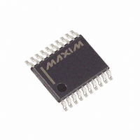
DS1867E-010+T&R Maxim Integrated Products, DS1867E-010+T&R Datasheet - Page 8

DS1867E-010+T&R
Manufacturer Part Number
DS1867E-010+T&R
Description
IC POT W/EEPROM DUAL 10K 20TSSOP
Manufacturer
Maxim Integrated Products
Datasheet
1.DS1867S-10.pdf
(14 pages)
Specifications of DS1867E-010+T&R
Taps
256
Resistance (ohms)
10K
Number Of Circuits
2
Temperature Coefficient
750 ppm/°C Typical
Memory Type
Non-Volatile
Interface
3-Wire Serial
Voltage - Supply
4.5 V ~ 5.5 V
Operating Temperature
-40°C ~ 85°C
Mounting Type
Surface Mount
Package / Case
20-TSSOP
Resistance In Ohms
10K
Lead Free Status / RoHS Status
Lead free / RoHS Compliant
DS1867
FIXED GAIN ATTENUATOR Figure 8
ABSOLUTE AND RELATIVE LINEARITY
Absolute linearity is defined as the difference between the actual measured output voltage and the
expected output voltage. Figure 9 presents the test circuit used to measure absolute linearity. Absolute
linearity is given in terms of a minimum increment or expected output when the wiper position is moved
one position. In the case of the test circuit, a minimum increment (MI) would equal 10/512volts. The
equation for absolute linearity is given in equation (1).
Eq: (1) Absolute Linearity
AL = {Vo(actual)- Vo(expected)}/MI
Relative linearity is a measure of error between two adjacent wiper position points and is given in terms
of MI by equation (2).
Eq: (2) Relative Linearity
RL = {Vo(n+1) - Vo(n)}/MI
Figure 10 is a plot of absolute linearity and relative linearity versus wiper position for the DS1867 at
25 C. The specification for absolute linearity of the DS1867 is 0.75 MI typical. The specification for
relative linearity of the DS1867 is 0.30 MI typical.
LINEARITY MEASUREMENT CONFIGURATION Figure 9
8 of 14
102199


