148384-5 TE Connectivity, 148384-5 Datasheet - Page 14
148384-5
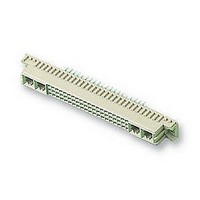
Manufacturer Part Number
148384-5
Description
SOCKET, DIN41612, STRAIGHT, M, 24+8WAY
Manufacturer
TE Connectivity
Datasheet
1.148384-5.pdf
(18 pages)
Specifications of 148384-5
Connector Type
Pitch Spacing
No. Of Contacts
32
Gender
Receptacle
No. Of Rows
3
Rows Loaded
A + B + C
Contact Termination
Through Hole
Contact Material
Phosphor Bronze
Contact
RoHS Compliant
Pitch Spacing
2.54mm
Contact Plating
Gold
Rohs Compliant
Yes
Product Series
Type M
Mount Angle
Vertical
Post Type
Compliant Post
Din Level
II
Loaded With Single Contacts Only
Yes
Color
Gray
Toolless (flat Rock)
Yes
Termination Post Length (mm [in])
6.00 [0.236]
Solder Tail Contact Plating
Tin-Lead over Nickel
Number Of Signal Contacts
24
Contact Type
Socket
Number Of Power Or Coaxial Contacts
8
Preloaded
Yes
Contact Configuration
Coaxial, Power
Contact Base Material
Phosphor Bronze
Contact Plating, Mating Area, Material
Gold Flash over Palladium Nickel
Connector Style
Receptacle
Housing Material
Thermoplastic - GF
Ul Flammability Rating
UL 94V-0
Rohs/elv Compliance
RoHS compliant, ELV compliant
Lead Free Solder Processes
Not relevant for lead free process
Rohs/elv Compliance History
Always was RoHS compliant
Pcb Thickness, Recommended (mm [in])
1.57 [0.062]
Application
Board-to-Board Power


3.9. Repair
In the event of damaged contacts or connector, the entire connector must be replaced with a new one, with the
exception of the coaxial contacts in Type M connectors which are removable (refer to Paragraph 5.6).
4. QUALIFICATIONS
Eurocard Connectors meet DIN 41612 and IEC 603--2 specifications. The connectors are also Certified by
CSA International in File LR7189 and Recognized under the Component Program of Underwriters Laboratories
Inc. (UL) in File E28476.
5. TOOLING
5.1. Application Tooling
For low--volume manufacturing, an arbor frame type applicator may be used; for high--volume manufacturing,
machine application is recommended. See Figure 13.
Power Units
14 of 18
CAUTION
DANGER
NOTE
C. Drying
When drying cleaned components and pc boards, make certain the temperature limitations of --55_ to
125_C [--70_ to 260_F] are not exceeded.
D. Soldering Guidelines
Refer to Paragraph 2.6 of this specification for instructional material that is available for establishing
soldering guidelines.
i
!
Typical Arbor Frame Press (Such as Greenerd 3A
or 3B Manual Frame Assembly—refer to 408- - 9027
for Adapter Kit when using this type press)
Consideration must be given to toxicity and safety requirements recommended on the Material Safety Data Sheet
furnished by the solvent manufacturer.
If you have a particular solvent that is not listed, consult an TE Representative before using it on these connectors.
Protect lower shroud (vertical connectors) or lower ground plane (enhanced connector) when soldering right- - angle pin
connectors.
SM- - 3 Machine
814700- - 2
Figure 13
“H” Frame Power Unit
Machine 803880- - 6
114- 9014
Rev G
Related parts for 148384-5
Image
Part Number
Description
Manufacturer
Datasheet
Request
R

Part Number:
Description:
Printers THERMAL PRINTER HS-SLEEVE MARKER
Manufacturer:
TE Connectivity


Part Number:
Description:
High Speed / Modular Connectors 30P HEADER ASSY
Manufacturer:
TE Connectivity
Datasheet:

Part Number:
Description:
High Speed / Modular Connectors REC 6X005P R/A LT B-PLANE HS3
Manufacturer:
TE Connectivity
Datasheet:

Part Number:
Description:
High Speed / Modular Connectors 2MM HM RCPT 50P R/A AU
Manufacturer:
TE Connectivity
Datasheet:

Part Number:
Description:
High Speed / Modular Connectors 2MM HM RCPT 50P R/A AU
Manufacturer:
TE Connectivity
Datasheet:


Part Number:
Description:
Manufacturer:
TE Connectivity
Datasheet:


Part Number:
Description:
Manufacturer:
TE Connectivity
Datasheet:

Part Number:
Description:
Manufacturer:
TE Connectivity
Datasheet:

Part Number:
Description:
Manufacturer:
TE Connectivity
Datasheet: