148384-5 TE Connectivity, 148384-5 Datasheet - Page 7
148384-5
Manufacturer Part Number
148384-5
Description
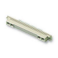
SOCKET, DIN41612, STRAIGHT, M, 24+8WAY
Manufacturer
TE Connectivity
Datasheet
1.148384-5.pdf
(18 pages)
Specifications of 148384-5
Connector Type
Pitch Spacing
No. Of Contacts
32
Gender
Receptacle
No. Of Rows
3
Rows Loaded
A + B + C
Contact Termination
Through Hole
Contact Material
Phosphor Bronze
Contact
RoHS Compliant
Pitch Spacing
2.54mm
Contact Plating
Gold
Rohs Compliant
Yes
Product Series
Type M
Mount Angle
Vertical
Post Type
Compliant Post
Din Level
II
Loaded With Single Contacts Only
Yes
Color
Gray
Toolless (flat Rock)
Yes
Termination Post Length (mm [in])
6.00 [0.236]
Solder Tail Contact Plating
Tin-Lead over Nickel
Number Of Signal Contacts
24
Contact Type
Socket
Number Of Power Or Coaxial Contacts
8
Preloaded
Yes
Contact Configuration
Coaxial, Power
Contact Base Material
Phosphor Bronze
Contact Plating, Mating Area, Material
Gold Flash over Palladium Nickel
Connector Style
Receptacle
Housing Material
Thermoplastic - GF
Ul Flammability Rating
UL 94V-0
Rohs/elv Compliance
RoHS compliant, ELV compliant
Lead Free Solder Processes
Not relevant for lead free process
Rohs/elv Compliance History
Always was RoHS compliant
Pcb Thickness, Recommended (mm [in])
1.57 [0.062]
Application
Board-to-Board Power


3.2. Housing Features
Surface Finish
HASL Sn Pb
Immersion Sn
OSP
Immersion Au/Ni
Immersion Ag
Rev G
Solder Tine Plated--Through
CONTACT
ACTION
TYPE
TYPE
PIN
C. Hole Dimensions
Values specified in the following must be complied with to ensure proper performance. The drilled hole
diameter and the copper plating thickness are of major importance and must be adhered to.
A. Boardlocks
The solder tine connectors are available with boardlocks which help retain the connector onto the pc
board. Special application tooling or equipment is not required for connectors with boardlocks.
B. Mounting Ears and Standoffs
These connectors are designed with mounting ears in different thicknesses and spacing between
standoffs. Those with larger mounting ear height and closer standoff spacing do not require a seating tool
to push the ACTION PIN contacts through the pc board holes to seat the connector. Those with smaller
mounting ear height and greater standoff spacing require the use of a seating tool. See Figure 4.
3.1.A.1 and .2 for PC
Refer to Paragraph
Board Thickness
Plated--Through
Plated--Through
Plated--Through
(Type Q)
TYPE
Non--
Thickness
0.008 [.0003] Min.
0.0005 [.000020] Min.
0.0002- - 0.0005 [.000008- - .000020]
0.004- - 0.005 Ni, 0.0001- - 0.0005 Au
[.00016- - .00020] Ni, [.000004- - .000020] Au
0.0001 [.000004] Min.
Finished Hole Dia.
After Plating
(Figure 3)
[.0443--.0463]
[.0344--.0364]
[.0443--.0463]
[.0443--.0463]
1.125--1.176
0.874--0.925
1.125--1.176
1.125--1.176
DRILLED
DIAMETER
PLATING (REF)
AFTER
[.040]
[.031]
[.039]
1.02
0.80
0.99
------
PC BOARD HOLE
Figure 3
(KNOOP- - 150 Max)
[.001- - .003]
[.001- - .003]
[.001- - .003]
0.03--0.08
0.03--0.08
0.03--0.08
COPPER
------
PLATING THICKNESS
See Surface Finish/Thickness
See Surface Finish/Thickness
See Surface Finish/Thickness
Callout in Above Illustration
Callout in Above Illustration
Drilled Hole Diameter
SURFACE
FINISH
------
Pad Diameter
Copper Plating
FR- - 4 Material (Ref)
PAD (MIN DIA)
PAD (MIN DIA)
Plus 0.51 [.020]
Hole Diameter
PC BOARD
1.57 [.062]
1.57 [.062]
1.65 [.065]
114- 9014
7 of 18
Related parts for 148384-5
Image
Part Number
Description
Manufacturer
Datasheet
Request
R

Part Number:
Description:
Printers THERMAL PRINTER HS-SLEEVE MARKER
Manufacturer:
TE Connectivity


Part Number:
Description:
High Speed / Modular Connectors 30P HEADER ASSY
Manufacturer:
TE Connectivity
Datasheet:

Part Number:
Description:
High Speed / Modular Connectors REC 6X005P R/A LT B-PLANE HS3
Manufacturer:
TE Connectivity
Datasheet:

Part Number:
Description:
High Speed / Modular Connectors 2MM HM RCPT 50P R/A AU
Manufacturer:
TE Connectivity
Datasheet:

Part Number:
Description:
High Speed / Modular Connectors 2MM HM RCPT 50P R/A AU
Manufacturer:
TE Connectivity
Datasheet:


Part Number:
Description:
Manufacturer:
TE Connectivity
Datasheet:


Part Number:
Description:
Manufacturer:
TE Connectivity
Datasheet:

Part Number:
Description:
Manufacturer:
TE Connectivity
Datasheet:

Part Number:
Description:
Manufacturer:
TE Connectivity
Datasheet: