63900-1 TE Connectivity, 63900-1 Datasheet - Page 21
63900-1
Manufacturer Part Number
63900-1
Description
TAB, FASTON 250 PCB 032TPCUBRLP
Manufacturer
TE Connectivity
Series
250r
Datasheet
1.63900-1.pdf
(44 pages)
Specifications of 63900-1
Connector Type
Tab Boardmount
Termination Method
Quick Disconnect
Stud/tab Size
0.25 X 0.032"
Contact Material
Brass
Contact Plating
Tin
Contact
RoHS Compliant
Product Type
Terminal
Terminal Type
Tab
Mating Area Interface Dimensions (mm [in])
6.35 x 0.81 [.250 x .032]
Finish
Tin
Mount Angle
Straight
Insulation Support
Without
Pcb Hole Diameter (mm [in])
1.40 [0.055]
Dimple
Without
Tab Type
Printed Circuit Board
Stud Hole
Without
Stock Thickness (mm [in])
0.81 [0.032]
Rohs/elv Compliance
RoHS compliant, ELV compliant
Lead Free Solder Processes
Wave solder capable to 240°C, Wave solder capable to 260°C, Wave solder capable to 265°C
Rohs/elv Compliance History
Always was RoHS compliant
Pcb Thickness, Recommended (mm [in])
3.18 [0.125]
Packaging Method
Loose Piece


Product Facts
■
■
■
■
■
■
■
■
■
■
Applications
■
■
■
■
■
Technical Documents
Application Specification
114-2051
Product Specification
108-2032
Catalog 82159
Revised 12-07
www.tycoelectronics.com
Redundant wire insulation
displacement termination
Built-in strain relief
Accepts 28-24 AWG
[0.09-0.2 mm
Feed-thru connections allow
wiring flexibility
Free-standing
Low board profile (less than
¼" [6.35 mm] high)
Available in loose piece or
strip form
Mass termination
adaptability
Capable of being reused
Low applied costs
Electronic games
Computer
Telephone equipment
Business machines
Electronic control
equipment
2
]
Dimensions are in inches and
millimeters unless otherwise
specified. Values in brackets
are metric equivalents.
Printed Circuit Board Terminals and Disconnects
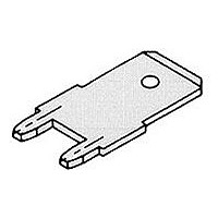
QUADRA-MATE Wire-to-Printed Circuit Board Terminal
The QUADRA-MATE Wire-
to-Printed Circuit Board
Terminal is an extension of
the MAG-MATE connector
program, and is designed
to terminate discrete wires
to a pc board via insulation
displacement slot
technology. It is capable of
accepting solid or stranded
wire and permits wire end
or feed-thru terminations.
The terminal features four
slots for redundant wire
terminations and strain
relief. The terminals are
installed in random
positions or in rows on the
edge of a pc board either
by hand tool, semiautomatic
or fully-automatic machines.
Thermal Shock Data for
Wire-to-Board Terminal
Cycles of Thermal Shock
Dimensions are shown for
reference purposes only.
Specifications subject
to change.
The terminal is compact in
design and readily
adaptable to a wide variety
of materials and plating
selections, as well as
terminating techniques
such as daisy chaining,
single ending and on-board
jumping and programming.
The .100 [2.54] wide
terminal has an overall
height of approximately
.210 [5.33] and occupies
less than .120 x .130 [3.05 x
3.3] of board area and
accommodates wire sizes
28-24 AWG [0.09-0.2 mm
(see table).
USA: 1-800-522-6752
Canada: 1-905-470-4425
Mexico: 01-800-733-8926
C. America: 52-55-1106-0803
Wire-to-Board
Competitive
Terminal
Terminal
24 AWG [0.2 mm
Solid Wire ––––––––
PVC Insulation
1 cycle = 1/2 hour at –65° and 1/2 hour at +125°C
2
]
2
The terminals are supplied
in both loose piece and
strip form and are easily
assembled to the pc board
in conjunction with on-board
components prior to wave
soldering. With the terminal
being an integral part of the
board, insertion of the
unstripped wire into the four
insulation displacement
slots is accomplished by
use of a simple hand tool
(see table).
]
South America: 55-11-2103-6000
Hong Kong: 852-2735-1628
Japan: 81-44-844-8013
UK: 44-8706-080-208
24 AWG [0.2 mm
Stranded Wire –– –– –– ––
PVC Insulation
2
]
21
Related parts for 63900-1
Image
Part Number
Description
Manufacturer
Datasheet
Request
R

Part Number:
Description:
Printers THERMAL PRINTER HS-SLEEVE MARKER
Manufacturer:
TE Connectivity


Part Number:
Description:
High Speed / Modular Connectors 30P HEADER ASSY
Manufacturer:
TE Connectivity
Datasheet:

Part Number:
Description:
High Speed / Modular Connectors REC 6X005P R/A LT B-PLANE HS3
Manufacturer:
TE Connectivity
Datasheet:

Part Number:
Description:
High Speed / Modular Connectors 2MM HM RCPT 50P R/A AU
Manufacturer:
TE Connectivity
Datasheet:

Part Number:
Description:
High Speed / Modular Connectors 2MM HM RCPT 50P R/A AU
Manufacturer:
TE Connectivity
Datasheet:


Part Number:
Description:
Manufacturer:
TE Connectivity
Datasheet:


Part Number:
Description:
Manufacturer:
TE Connectivity
Datasheet:

Part Number:
Description:
Manufacturer:
TE Connectivity
Datasheet:

Part Number:
Description:
Manufacturer:
TE Connectivity
Datasheet: