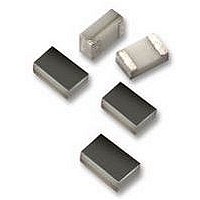
04023J3R9CBSTR AVX Corporation, 04023J3R9CBSTR Datasheet - Page 123

04023J3R9CBSTR
Manufacturer Part Number
04023J3R9CBSTR
Description
CAPACITOR, ACCU-P 3.9PF 25V 0402CAPACITOR, ACCU-P 3.9PF 25V 0402
Manufacturer
AVX Corporation
Datasheet
1.04023J3R9CBSTR.pdf
(148 pages)
Specifications of 04023J3R9CBSTR
Capacitance
3.9PF
Voltage Rating, Dc
25V
Capacitor Dielectric Type
CERAMIC MULTI-LAYER
Tolerance,
6.4%
Tolerance, -
6.4%
Temp, Op. Max
125(DEGREE C)
Temp, Op.
ROHS COMPLIANT
- Current page: 123 of 148
- Download datasheet (4Mb)
6
Microwave MLC’s
CDR Series — MIL-PRF-55681 (RF/Microwave Chips)
MILITARY DESIGNATION PER MIL-PRF-55681
CROSS REFERENCE: AVX/MIL-PRF-55681
HOW TO ORDER
122
PACKAGING
Standard Packaging Quanity
CDR11-12 = 100 pcs per waffle pack
CDR13-14 = 80 pcs per waffle pack
TAPE & REEL:
Sizes SQCA through SQCB, CDR11/12 through 13/14.
—8mm carrier
—7" reel: ≤0.040" thickness = 2000 pcs
—13" reel: ≤0.075" thickness = 10,000 pcs
CDR11, CDR12,
Per MIL-C-55681
CDR13, CDR14
MIL Style
CDR12
CDR11
CDR12
CDR13
CDR14
T
CDR11/12
≤0.075" thickness = 2000 pcs
W
bw
BG = +90±20 ppm/°C with and without
BP = 0±30ppm/°C with and without
rated voltage from -55°C to +125°C
rated voltage from -55°C to + 125°C
L
All tape and reel specifications are in compliance with EIA RS481 (equivalent to IEC 286 part 3).
Temperature
AQ11
AQ12
AQ13
AQ14
Voltage
Style
Limits
AVX
BG
T
W
bw
EIA Capacitance Code in pF.
First two digits = significant figures
or “R” for decimal place.
Third digit = number of zeros or
after “R” significant figures.
CDR13/14
(2.79 +.889 -.508)
.110 +.035 -0.20
Capacitance
(1.40±.381)
(1.40±.635)
(2.79±.508)
Length (L)
.055±.015
.055±.025
.110±.020
101
L
Rated Voltage
B = 100V
C = 200V
D = 300V
A = 50V
E = 500V
(1.40±.381)
(1.40±.381)
(2.79±.508)
(2.79±.508)
Width (W)
.055±.015
.055±.015
.110±.020
.110±.020
Code
A
Tolerance Code
Capacitance
M = ±20%
G = ±2%
B = ±.1 pF
C = ±.25 pF
D = ±.5 pF
K = ±10%
F = ±1%
J = ±5%
(1.45)
(1.45)
(2.59)
(2.59)
.057
.057
.102
.102
Max
K
Thickness (T)
W = Base Metallization, Barrier Metal,
M = Palladium/Silver (CDR11 & 13 only)
N = Silver, Nickel, Gold (CDR11 & 13 only)
U = Base Metallization, Barrier Metal, Solder
S = Solder Coated, Final (CDR12 & 14 only)
Y = 100% Tin
Z = Base Metallization, Barrier Metal
(.508)
(.508)
(.762)
(.762)
Finish (Military
.020
.020
.030
.030
Designations)
Min
Termination
Coated. (Solder M.P. 200°C or less)
(CDR12 & 14 only)
Tinned (Tin or Tin/Lead Alloy)
(CDR12 & 14 only)
(TIn Lead Alloy With 4% Lead Min.)
Code
U
Termination Band (bw)
(.508)
(.508)
(.635)
(.635)
Max
.020
.020
.025
.025
Failure Rate
M = 1.0%
P = .1%
R = .01%
S = .001%
Level
S
(.127)
(.127)
(.127)
(.127)
.005
.005
.005
.005
Min
Related parts for 04023J3R9CBSTR
Image
Part Number
Description
Manufacturer
Datasheet
Request
R

Part Number:
Description:
Manufacturer:
AVX Corporation
Datasheet:

Part Number:
Description:
Manufacturer:
AVX Corporation
Datasheet:

Part Number:
Description:
Manufacturer:
AVX Corporation
Datasheet:

Part Number:
Description:
Manufacturer:
AVX Corporation
Datasheet:

Part Number:
Description:
Manufacturer:
AVX Corporation
Datasheet:


