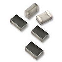
04023J3R9CBSTR AVX Corporation, 04023J3R9CBSTR Datasheet - Page 131

04023J3R9CBSTR
Manufacturer Part Number
04023J3R9CBSTR
Description
CAPACITOR, ACCU-P 3.9PF 25V 0402CAPACITOR, ACCU-P 3.9PF 25V 0402
Manufacturer
AVX Corporation
Datasheet
1.04023J3R9CBSTR.pdf
(148 pages)
Specifications of 04023J3R9CBSTR
Capacitance
3.9PF
Voltage Rating, Dc
25V
Capacitor Dielectric Type
CERAMIC MULTI-LAYER
Tolerance,
6.4%
Tolerance, -
6.4%
Temp, Op. Max
125(DEGREE C)
Temp, Op.
ROHS COMPLIANT
- Current page: 131 of 148
- Download datasheet (4Mb)
6
Microwave MLC’s
Automatic Insertion Packaging
TAPE & REEL:
Sizes SQCA through SQCB, CDR11/12 through 13/14.
—8mm carrier
—7" reel: ≤0.040" thickness = 2000 pcs
—13" reel: ≤0.075" thickness = 10,000 pcs
EMBOSSED CARRIER CONFIGURATION
8 & 12 MM TAPE ONLY
CONSTANT DIMENSIONS
VARIABLE DIMENSIONS
130
REEL DIMENSIONS
NOTES:
1. A
2. Tape with components shall pass around radius “R” without damage. The
12mm
8mm
Tape
Size
and
terminals extending from the component body and/or the body dimensions of
the component. The clearance between the end of the terminals or body of the
component to the sides and depth of the cavity (A
0.05 mm (.002) min. and 0.50 mm (.020) max. The clearance allowed must also
prevent rotation of the component within the cavity of not more than 20 degrees
(see sketches C & D).
minimum trailer length (Note 2 Fig. 3) may require additional length to provide R
min. for 12mm embossed tape for reels with hub diameters approaching N min.
(Table 4).
Tape Size
12mm
8mm
0,
B
0,
(.059
and K
≤0.075" thickness = 2000 pcs
8.4
D
0
-0.0
+0.10
+.004
-0.0
0
are determined by the max. dimensions to the ends of the
)
See Note 6
(.179)
(.323)
All tape and reel specifications are in compliance with EIA RS481 (equivalent to IEC 286 part 3).
Max.
4.55
(.069 ± .004)
1.75 ± 0.10
8.2
B
1
E
:
millimeters (inches)
See Note 5
(.157 ± .004) (.079 ± .002) (.024) (.004) (.030) (.030)
(.039)
(.059)
Min.
4.0 ± 0.10
1.0
1.5
D
1
P
0
0,
B
0,
(.138 ± .002)
(.217 ± .002)
3.5 ± 0.05
5.5 ± 0.05
2.0 ± 0.05
and K
P
F
2
0
) must be within
0.600
Max.
T
(.157 ± .004)
(.157 ± .004)
4.0 ± 0.10
4.0 ± 0.10
Max.
0.10
T
P
1
1
Metric dimensions will govern.
English measurements rounded and for reference only.
(1) For tape sizes 16mm and 24mm (used with chip size 3640) consult EIA RS-481 latest revision.
12mm
Size
8mm
Tape
Note 3
3. G
4. G
5. The embossment hole location shall be measured from the sprocket hole
6. B
0.75
Min.
See
G
“U” Series - 402/0603/0805/1210 Size Chips
—8mm carrier
—7" reel: 0402 = 10,000 pcs
—13" reel: ≤0.075" thickness = 10,000 pcs
(1)
outward deformation of the carrier tape between the embossed cavities or to
the edge of the cavity whichever is less.
sprocket holes to either the outward deformation of the carrier tape between the
embossed cavity or to the edge of the cavity whichever is less.
controlling the location of the embossment. Dimensions of embossment
location and hole location shall be applied independent of each other.
1
1
1
2
dimension is a reference dimension for tape feeder clearance only.
(12.992) (.059) (.512±.008) (.795) (1.969)
dimension is the flat area from the edge of the sprocket hole to either the
dimension is the flat area from the edge of the carrier tape opposite the
Max. Min.
Note 4
330
0.75
Min.
See
A
G
See Note 2
2
(1.181)
(.984)
Min.
25
30
R
0805 . 0.040" thickness & 1210 = 2000 pcs
0603 & 0805 ≤0.40" thickness = 4000 pcs
1.5
B*
13.0±0.20 20.2
C
2.5 Max
6.5 Max
(.098)
(.256)
T
2
Min. Min.
D*
50
(.472 ± .012)
N
12.0 ± .30
(.315
8.0
W
(.488
(.331
+0.3
-0.1
+.012
12.4
-.004
8.4
W
)
1
+ 1.0
+.060
-0.0
-0.0
+.076
+2.0
-0.0
-0.0
) (.567) 10.9 Max.
) (.724) 15.4 Max.
Max.
14.4
18.4
W
See Note 1
See Note 1
2
A
0
B
11.9 Min.
0
7.9 Min.
K
(.311)
(.429)
(.469)
(.607)
0
W
3
Related parts for 04023J3R9CBSTR
Image
Part Number
Description
Manufacturer
Datasheet
Request
R

Part Number:
Description:
Manufacturer:
AVX Corporation
Datasheet:

Part Number:
Description:
Manufacturer:
AVX Corporation
Datasheet:

Part Number:
Description:
Manufacturer:
AVX Corporation
Datasheet:

Part Number:
Description:
Manufacturer:
AVX Corporation
Datasheet:

Part Number:
Description:
Manufacturer:
AVX Corporation
Datasheet:


