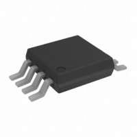
AD5626BRMZ Analog Devices Inc, AD5626BRMZ Datasheet - Page 10

AD5626BRMZ
Manufacturer Part Number
AD5626BRMZ
Description
IC DAC NANO 12BIT 8-MSOP
Manufacturer
Analog Devices Inc
Series
nanoDAC™r
Specifications of AD5626BRMZ
Data Interface
Serial
Settling Time
16µs
Number Of Bits
12
Number Of Converters
1
Voltage Supply Source
Single Supply
Power Dissipation (max)
12.5mW
Operating Temperature
-40°C ~ 85°C
Mounting Type
Surface Mount
Package / Case
8-MSOP, Micro8™, 8-uMAX, 8-uSOP,
Resolution (bits)
12bit
Sampling Rate
2MSPS
Input Channel Type
Serial
Supply Voltage Range - Analogue
4.75V To 5.25V
Supply Current
1.5mA
Digital Ic Case Style
SOP
No. Of
RoHS Compliant
Lead Free Status / RoHS Status
Lead free / RoHS Compliant
Available stocks
Company
Part Number
Manufacturer
Quantity
Price
Part Number:
AD5626BRMZ
Manufacturer:
ADI/亚德诺
Quantity:
20 000
Part Number:
AD5626BRMZ-REEL7
Manufacturer:
ADI/亚德诺
Quantity:
20 000
AD5626
THEORY OF OPERATION
The AD5626 is a complete, ready-to-use, 12-bit digital-to-analog
converter (DAC). It contains a voltage-switched, 12-bit, laser-
trimmed DAC, a curvature-corrected band gap reference, a
rail-to-rail output op amp, a DAC register, and a serial data
input register. The serial data interface consists of an SCLK,
serial data in (SDIN), and a load strobe ( LDAC ). This basic
3-wire interface offers maximum flexibility for interface to the
widest variety of serial data input loading requirements. In
addition, a CS select is provided for multiple packaging loading
and a power-on-reset CLR pin to simplify start or periodic resets.
DAC SECTION
The DAC is a 12-bit voltage mode device with an output that
swings from the GND potential to the 2.5 V internal band gap
voltage. It uses a laser trimmed, rail-to-rail ladder which is
switched by N-channel MOSFETs. The output voltage of the
DAC has a constant resistance independent of digital input
code. The DAC output internally connects to the rail-to-rail
output op amp.
AMPLIFIER SECTION
A low power consumption, precision amplifier buffers the DAC
output. This amplifier contains a differential PNP pair input
stage that provides low offset voltage and low noise, as well as
the ability to amplify the zero-scale DAC output voltages.
The rail-to-rail amplifier is configured with a gain of 1.6384
(= 4.095 V/2.5 V) to set the 4.095 V full-scale output (1 mV/LSB).
See Figure 23 for an equivalent circuit schematic of the analog
section.
The op amp has a 16 μs typical settling time to 0.01%. There are
slight differences in settling time for negative slewing signals vs.
positive slewing signals. See the oscilloscope photos in the
Typical Performance Characteristics section of this data sheet.
OUTPUT SECTION
The rail-to-rail output stage of this amplifier is designed to
provide precision performance when operating near either
power supply.
REFERENCE
BAND GAP
Figure 23. Equivalent AD5626 Schematic of Analog Section
2.5V
N-CHANNEL FET
BUFFER
SWITCHES
VOLTAGE SWITCHED 12-BIT
RAIL-TO-RAIL CONVERTER
SPDT
2R
2R
2R
2R
2R
R
R
A
(= 4.095V/2.5V)
V
R1
= 1.638
R2
RAIL-TO-RAIL
OUTPUT
AMPLIFIER
V
OUT
Rev. A | Page 10 of 20
Figure 24 shows an equivalent output schematic of the rail-to-
rail amplifier with its N-channel pull-down FETs that pull an
output load directly to GND. The output sourcing current is
provided by a P-channel pull-up device that can supply GND
terminated loads, especially at the low supply tolerance values
of 4.75 V. Figure 5 and Figure 6 provide information on output
swing performance near ground and full-scale as a function of
load. In addition to resistive load driving capability, the amplifier
has also been carefully designed and characterized for up to
500 pF capacitive load driving capability.
POWER SUPPLY
The very low power consumption of the AD5626 is a direct
result of a circuit design optimizing use of the CBCMOS process.
By using the low power characteristics of the CMOS for the
logic, and the low noise, tight matching of the complementary
bipolar transistors, good analog accuracy is achieved.
For power consumption sensitive applications, it is important
to note that the internal power consumption of the AD5626
is strongly dependent on the actual logic input voltage levels
present on the SDIN, CS , LDAC , and CLR pins. Because these
inputs are standard CMOS logic structures, they contribute
static power dissipation dependent on the actual driving
Logic V
shows the effect on total AD5626 supply current as a function
of the actual value of input logic voltage. Consequently, use of
CMOS logic vs. TTL minimizes power dissipation in the static
state. A V
lowest standby power dissipation of 2.5 mW (500 μA × 5 V).
As with any analog system, it is recommended that the AD5626
power supply be bypassed on the same PC card that contains
the chip. Figure 10 shows the power supply rejection vs. frequency
performance. This should be taken into account when using higher
frequency, switched mode power supplies with ripple frequencies
of 100 kHz and higher.
One advantage of the rail-to-rail output amplifier used in the
AD5626 is the wide range of usable supply voltage. The part is
fully specified and tested over temperature for operation from
4.75 V to 5.25 V. If reduced linearity and source current capa-
bility near full scale can be tolerated, operation of the AD5626
is possible down to 4.3 V. The minimum operating supply
OH
IL
and Logic V
= 0 V on the SDIN,
Figure 24. Equivalent Analog Output Circuit
OL
voltage levels. The graph in
N-CH
P-CH
CS , and CLR pins provides the
V
V
AGND
DD
OUT
Figure 9


