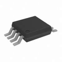
AD5626BRMZ Analog Devices Inc, AD5626BRMZ Datasheet - Page 15

AD5626BRMZ
Manufacturer Part Number
AD5626BRMZ
Description
IC DAC NANO 12BIT 8-MSOP
Manufacturer
Analog Devices Inc
Series
nanoDAC™r
Specifications of AD5626BRMZ
Data Interface
Serial
Settling Time
16µs
Number Of Bits
12
Number Of Converters
1
Voltage Supply Source
Single Supply
Power Dissipation (max)
12.5mW
Operating Temperature
-40°C ~ 85°C
Mounting Type
Surface Mount
Package / Case
8-MSOP, Micro8™, 8-uMAX, 8-uSOP,
Resolution (bits)
12bit
Sampling Rate
2MSPS
Input Channel Type
Serial
Supply Voltage Range - Analogue
4.75V To 5.25V
Supply Current
1.5mA
Digital Ic Case Style
SOP
No. Of
RoHS Compliant
Lead Free Status / RoHS Status
Lead free / RoHS Compliant
Available stocks
Company
Part Number
Manufacturer
Quantity
Price
Part Number:
AD5626BRMZ
Manufacturer:
ADI/亚德诺
Quantity:
20 000
Part Number:
AD5626BRMZ-REEL7
Manufacturer:
ADI/亚德诺
Quantity:
20 000
For the ±2.5 V output range and the circuit values shown in the
table in Figure 31, the transfer equation becomes
Similarly, for the 5 V output range, the transfer equation
becomes
GENERATING A NEGATIVE SUPPLY VOLTAGE
Some applications may require bipolar output configuration
but only have a single power supply rail available. This is very
common in data acquisition systems using microprocessor-
based systems. In these systems, only 12 V, 15 V, and/or 5 V
are available.
Figure 32 shows a method for generating a negative supply
voltage using one CD4049, a CMOS hexadecimal inverter, and
operating on 12 V or 15 V. The circuit is essentially a charge
pump where two of the six inverters are used as an oscillator.
For the values shown, the frequency of oscillation is approx-
imately 3.5 kHz and is fairly insensitive to supply voltage
because R1 > 2 × R2.
The remaining four inverters are wired in parallel for higher
output current. The square wave output is level translated by C2
to a negative-going signal rectified using a pair of 1N4001s, and
then filtered by C3. With the values shown, the charge pump
provides an output voltage of −5 V for currents loading in the
range 0.5 mA ≤ I
I
A SINGLE-SUPPLY, PROGRAMMABLE
CURRENT SOURCE
The circuit in Figure 33 shows how the AD5626 can be used
with an OP295 single-supply, rail-to-rail, output op amp to
provide a digitally programmable current sink from V
that consumes less than 3.8 mA, maximum. The DAC output
voltage is applied across R1 by placing the 2N2222 transistor in
the feedback loop of the OP295. For the circuit values shown,
the full-scale output current is 1 mA, which is given by the
following equation:
where DW = the binary digital input code of the AD5626.
INVERTERS = CD4049
OUT
R1
510kΩ
Figure 32. Generating a –5 V Supply When Only 12 V or 15 V Is Available
3
≤ 7 mA with a 12 V supply.
V
V
I
OUT
O
O
2
= 1.22 mV × Digital Code − 2.5 V
= 2.44 mV × Digital Code − 5 V
R2
5.1kΩ
=
5
0.02µF
DW
C1
4
OUT
×
R1
. 4
≤ 10 mA with a 15 V supply and 0.5 mA ≤
095
11
14
7
9
V
10
12
15
6
+
47µF
C2
D1
1N4001
1N4001
D2
C3
47µF
470Ω
R3
SOURCE
1N5231
5.1V
ZENER
–5V
Rev. A | Page 15 of 20
The usable output voltage range of the current sink is 5 V to
60 V. The low limit of the range is controlled by transistor
saturation, and the high limit is controlled by the collector-base
breakdown voltage of the 2N2222.
GALVANICALLY-ISOLATED INTERFACE
In many process control type applications, it is necessary to
provide an isolation barrier between the controller and the unit
being controlled to protect and isolate the controlling circuitry
from any hazardous common-mode voltages that may occur.
An iCoupler® can provide isolation in excess of 2.5 kV. The
serial loading structure of the AD5626 makes it ideal for
isolated interfaces as the number of interface lines is kept to
a minimum. Figure 34 illustrates a 4-channel isolated interface
using an ADuM1400. For further information, visit
http://www.analog.com/icouplers.
LDAC
SCLK
SDIN
MICROCONTROLLER
*ADDITIONAL PINS OMITTED FOR CLARITY.
CLR
SERIAL CLOCK OUT
CS
SERIAL DATA OUT
CONTROL OUT
Figure 33. A Single-Supply, Programmable Current Source
2
6
5
3
4
SYNC OUT
Figure 34. An iCoupler-Isolated DAC Interface
AD5626
GND
V
5V
DD
1
7
V IA
V IB
V IC
V ID
0.1µF
V
OUT
8
ENCODE
ENCODE
ENCODE
ENCODE
A1 = 1/2 OP295
ADuM1400*
3
2
+
–
A1
+5V
DECODE
DECODE
DECODE
DECODE
1
V
V OA
V OB
V OC
V OD
S
LOAD
2N2222
R1
4.02kΩ
P1
200Ω
FULL-SCALE
ADJUST
AD5626
TO SCLK
TO SDIN
TO LDAC
TO SYNC


