AD7837AQ Analog Devices Inc, AD7837AQ Datasheet - Page 10
AD7837AQ
Manufacturer Part Number
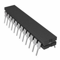
AD7837AQ
Description
IC DAC 12BIT DUAL MULT 24-CDIP
Manufacturer
Analog Devices Inc
Datasheet
1.AD7837ARZ.pdf
(12 pages)
Specifications of AD7837AQ
Rohs Status
RoHS non-compliant
Settling Time
4µs
Number Of Bits
12
Data Interface
Parallel
Number Of Converters
2
Voltage Supply Source
Dual ±
Power Dissipation (max)
210mW
Operating Temperature
-40°C ~ 85°C
Mounting Type
Through Hole
Package / Case
24-CDIP (0.300", 7.62mm)


AD7837/AD7847
ANALOG PANNING CIRCUIT
In audio applications it is often necessary to digitally “pan” or
split a single signal source into a two-channel signal while main-
taining the total power delivered to both channels constant. This
may be done very simply by feeding the signal into the V
input of both DACs. The digital codes are chosen such that the
code applied to DAC B is the two's complement of that applied
to DAC A. In this way the signal may be panned between both
channels as the digital code is changed. The total power varia-
tion with this arrangement is 3 dB.
For applications which require more precise power control the
circuit shown in Figure 18 may be used. This circuit requires
the AD7837/AD7847, an AD712 dual op amp and eight equal
value resistors.
Again both channels are driven with two's complementary data.
The maximum power variation using this circuit is only 0.5 dBs.
The voltage output expressions for the two channels are as
follows:
where N
and N
with N
The two's complement relationship between N
N
Hence N
With N
condition where the power is split equally between both chan-
nels. The total power variation as the signal is fully panned from
Channel B to Channel A is shown in Figure 19.
B
to increase as N
V
B
B
IN
A
= DAC B input code in decimal (1 ≤ N
A
= 2s complement of N
A
= 2048, then N
= DAC A input code in decimal (1 ≤ N
+ N
B
R
R
R
R
= 4096.
V
V
A
OUTA
OUT B
decreases and vice versa.
AD712
AD712
B
1/2
1/2
R
R
= –V
= –V
= 2048 also; this gives the balanced
R
R
V
OUTA
IN
A
IN
.
RL
2
2
A
12
12
N
N
+ N
+ N
A
B
RL
A
B
B
V
V
V
V
V
OUTA
OUTB
REFA
REFB
OUTB
A
B
AD7837/
AD7847
and N
≤ 4095)
A
≤ 4095)
B
causes
REF
APPLYING THE AD7837/AD7847
General Ground Management
AC or transient voltages between the analog and digital grounds
i.e., between AGNDA/AGNDB and DGND can cause noise
injection into the analog output. The best method of ensuring
that both AGNDs and DGND are equal is to connect them
together at the AD7837/AD7847 on the circuit board. In more
complex systems where the AGND and DGND intertie is on the
backplane, it is recommended that two diodes be connected in
inverse parallel between the AGND and DGND pins (1N914 or
equivalent).
Power Supply Decoupling
In order to minimize noise it is recommended that the V
the V
using a 10 µF in parallel with a 0.1 µF ceramic capacitor.
Operation with Reduced Power Supply Voltages
The AD7837/AD7847 is specified for operation with V
± 15 V ± 5%. The part may be operated down to V
± 10 V without significant linearity degradation. See typical
performance graphs. The output amplifier however requires
approximately 3 V of headroom so the V
approach within 3 V of either power supply voltages in order to
maintain accuracy.
MICROPROCESSOR INTERFACING–AD7847
Figures 20 to 22 show interfaces between the AD7847 and three
popular 16-bit microprocessor systems, the 8086, MC68000 and
the TMS320C10. In all interfaces, the AD7847 is memory-
mapped with a separate memory address for each DAC latch.
AD7847–8086 Interface
Figure 20 shows an interface between the AD7847 and the 8086
microprocessor. A single MOV instruction loads the 12-bit word
into the selected DAC latch and the output responds on the ris-
ing edge of WR.
SS
0.0
0.6
0.5
0.4
0.3
0.2
0.1
lines on the AD7837/AD7847 be decoupled to DGND
1
512
1024
DIGITAL INPUT CODE N
1536
2048
2560
A
REF
3072
input should not
3584
DD
/V
4095
DD
SS
DD
/V
=
and
SS
=
Related parts for AD7837AQ
Image
Part Number
Description
Manufacturer
Datasheet
Request
R

Part Number:
Description:
±1.7g Dual-Axis IMEMS Accelerometer Evaluation Board
Manufacturer:
Analog Devices Inc
Datasheet:

Part Number:
Description:
Inertial Sensor Evaluation System
Manufacturer:
Analog Devices Inc
Datasheet:
Part Number:
Description:
Manufacturer:
Analog Devices Inc
Datasheet:
Part Number:
Description:
Manufacturer:
Analog Devices Inc
Datasheet:
Part Number:
Description:
Manufacturer:
Analog Devices Inc
Datasheet:
Part Number:
Description:
Manufacturer:
Analog Devices Inc
Datasheet:
Part Number:
Description:
Manufacturer:
Analog Devices Inc
Datasheet:
Part Number:
Description:
Manufacturer:
Analog Devices Inc
Datasheet:
Part Number:
Description:
Manufacturer:
Analog Devices Inc
Datasheet:
Part Number:
Description:
Manufacturer:
Analog Devices Inc
Datasheet:
Part Number:
Description:
Manufacturer:
Analog Devices Inc
Datasheet:
Part Number:
Description:
Manufacturer:
Analog Devices Inc
Datasheet:
Part Number:
Description:
Manufacturer:
Analog Devices Inc
Datasheet: