AD7837AQ Analog Devices Inc, AD7837AQ Datasheet - Page 9
AD7837AQ
Manufacturer Part Number
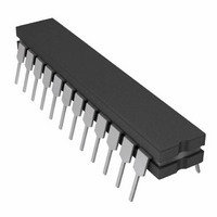
AD7837AQ
Description
IC DAC 12BIT DUAL MULT 24-CDIP
Manufacturer
Analog Devices Inc
Datasheet
1.AD7837ARZ.pdf
(12 pages)
Specifications of AD7837AQ
Rohs Status
RoHS non-compliant
Settling Time
4µs
Number Of Bits
12
Data Interface
Parallel
Number Of Converters
2
Voltage Supply Source
Dual ±
Power Dissipation (max)
210mW
Operating Temperature
-40°C ~ 85°C
Mounting Type
Through Hole
Package / Case
24-CDIP (0.300", 7.62mm)


BIPOLAR OPERATION
(4-QUADRANT MULTIPLICATION)
Figure 16 shows the AD7837/AD7847 connected for bipolar
operation. The coding is offset binary as shown in Table IV.
When V
plication. To maintain the gain error specifications, resistors R1,
R2 and R3 should be ratio matched to 0.01%. Note that on the
AD7847 the feedback resistor R
V
DAC Latch Contents
MSB
1111 1111 1111
1000 0000 0001
1000 0000 0000
0111 1111 1111
0000 0000 0000
Note 1 LSB =
OUT
V
IN
.
IN
V
is an ac signal, the circuit performs 4-quadrant multi-
REFA
AD7837
AD7847
LSB
2048
DGND
V
IN
Table IV. Bipolar Code Table
DAC A
.
AGNDA
V
V
DD
DD
20k
V
V
R1
FB
SS
SS
V
R
OUTA
FBA
is internally connected to
Analog Output, V
0 V
+V
+V
–V
–V
IN
IN
IN
IN
INTERNALLY
CONNECTED
ON AD7847
×
×
×
×
R3
10k
2048
2048
2048
2048
2047
2048
AD711
20k
1
1
R2
= –V
OUT
V
OUT
IN
APPLICATIONS
PROGRAMMABLE GAIN AMPLIFIER (PGA)
The dual DAC/amplifier combination along with access to R
make the AD7837 ideal as a programmable gain amplifier. In this
application, the DAC functions as a programmable resistor in the
amplifier feedback loop. This type of configuration is shown
in Figure 17 and is suitable for ac gain control. The circuit con-
sists of two PGAs in series. Use of a dual configuration provides
greater accuracy over a wider dynamic range than a single PGA
solution. The overall system gain is the product of the individual
gain stages. The effective gains for each stage are controlled by
the DAC codes. As the code decreases, the effective DAC
resistance increases, and so the gain also increases.
The transfer function is given by
where R
by the digital input code:
where R
N = DAC input code in decimal.
The transfer function in (1) thus simplifies to
where N
input code in decimal.
N
code is not allowed as it results in an open loop amplifier
response. To minimize errors, the digital codes N
should be chosen to be equal to or as close as possible to each
other to achieve the required gain.
A
, N
V
B
OUT
V
may be programmed between 1 and (2
EQA
IN
IN
A
= DAC A input code in decimal and N
is the DAC input resistance and is equal to R
, R
V
R
V
V
V
OUT
EQ
OUT
EQB
IN
IN
=
are the effective DAC resistances controlled
V
=
R
AGNDA
V
2
=
REFB
OUTB
FBA
12
R
R
N
N
2
R
EQA
FBA
12
A
IN
×
DAC B
×
N
2
R
R
12
B
EQB
FBB
AD7837/AD7847
DAC A
AD7837
AGNDB
V
V
R
12
REFA
OUTA
FBB
–1). The zero
B
= DAC B
A
and N
FB
and
B
(1)
(3)
(2)
FB
Related parts for AD7837AQ
Image
Part Number
Description
Manufacturer
Datasheet
Request
R

Part Number:
Description:
±1.7g Dual-Axis IMEMS Accelerometer Evaluation Board
Manufacturer:
Analog Devices Inc
Datasheet:

Part Number:
Description:
Inertial Sensor Evaluation System
Manufacturer:
Analog Devices Inc
Datasheet:
Part Number:
Description:
Manufacturer:
Analog Devices Inc
Datasheet:
Part Number:
Description:
Manufacturer:
Analog Devices Inc
Datasheet:
Part Number:
Description:
Manufacturer:
Analog Devices Inc
Datasheet:
Part Number:
Description:
Manufacturer:
Analog Devices Inc
Datasheet:
Part Number:
Description:
Manufacturer:
Analog Devices Inc
Datasheet:
Part Number:
Description:
Manufacturer:
Analog Devices Inc
Datasheet:
Part Number:
Description:
Manufacturer:
Analog Devices Inc
Datasheet:
Part Number:
Description:
Manufacturer:
Analog Devices Inc
Datasheet:
Part Number:
Description:
Manufacturer:
Analog Devices Inc
Datasheet:
Part Number:
Description:
Manufacturer:
Analog Devices Inc
Datasheet:
Part Number:
Description:
Manufacturer:
Analog Devices Inc
Datasheet: