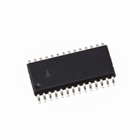
HI5735KCB Intersil, HI5735KCB Datasheet - Page 4

HI5735KCB
Manufacturer Part Number
HI5735KCB
Description
IC DAC 12-BIT 80MSPS 28-SOIC
Manufacturer
Intersil
Datasheet
1.HI5735KCBZ.pdf
(11 pages)
Specifications of HI5735KCB
Settling Time
20ns
Number Of Bits
12
Data Interface
Parallel
Number Of Converters
1
Voltage Supply Source
Analog and Digital, Dual ±
Power Dissipation (max)
650mW
Operating Temperature
0°C ~ 70°C
Mounting Type
Surface Mount
Package / Case
28-SOIC (7.5mm Width)
Lead Free Status / RoHS Status
Contains lead / RoHS non-compliant
Available stocks
Company
Part Number
Manufacturer
Quantity
Price
Part Number:
HI5735KCB
Manufacturer:
INTERSIL
Quantity:
20 000
Company:
Part Number:
HI5735KCBZ
Manufacturer:
MAXIM
Quantity:
1 001
Electrical Specifications
NOTES:
REFERENCE/CONTROL AMPLIFIER
Internal Reference Voltage, V
Internal Reference Voltage Drift
Internal Reference Output Current Sink/Source
Capability
Internal Reference Load Regulation
Input Impedance at REF OUT pin
Amplifier Large Signal Bandwidth (0.6V
Amplifier Small Signal Bandwidth (0.1V
Reference Input Impedance
Reference Input Multiplying Bandwidth (CTL IN)
DIGITAL INPUTS (D9-D0, CLK, INVERT)
Input Logic High Voltage, V
Input Logic Low Voltage, V
Input Logic Current, I
Input Logic Current, I
Digital Input Capacitance, C
TIMING CHARACTERISTICS
Data Setup Time, t
Data Hold Time, t
Propagation Delay Time, t
CLK Pulse Width, t
POWER SUPPLY CHARACTERISITICS
I
I
I
Power Dissipation
Power Supply Rejection Ratio
2. Gain Error measured as the error in the ratio between the full scale output current and the current through R
3. Parameter guaranteed by design or characterization and not production tested.
4. All devices are 100% tested at 25
5. Dynamic Range must be limited to a 1V swing within the compliance range.
EEA
EED
CCD
ratio should be 16.
industrial temperature devices.
HLD
PARAMETER
SU
PW1
IH
IL
, t
PW2
PD
IL
IH
IN
REF
4
AV
o
EE
C. 100% production tested at temperature extremes for military temperature devices, sample tested for
P-P
P-P
, DV
)
)
EE
= -4.94 to -5.46V, V
(Note 3)
(Note 4)
(Note 3)
(Note 3)
I
(Note 3)
Sine Wave Input, to Slew Rate Limited (Note 3)
Sine Wave Input, to -3dB Loss (Note 3)
R
(Note 3)
(Note 4)
(Note 4)
(Note 4)
(Note 4)
(Note 3)
See Figure 1 (Note 3)
See Figure 1 (Note 3)
See Figure 1 (Note 3)
See Figure 1 (Note 3)
(Note 4)
(Note 4)
(Note 4)
(Note 4)
V
REF
CC
L
= 50Ω, 100mV Sine Wave, to -3dB Loss at I
±5%, V
= 0 to I
REF
EE
HI5735
CC
±5%
TEST CONDITIONS
= -125µA
= +4.75 to +5.25V, V
REF
= Internal T
OUT
A
= 25
-1.27
-125
MIN
2.0
3.0
0.5
3.0
SET
-
-
-
-
-
-
-
-
-
-
-
-
-
-
-
-
-
o
C for All Typical Values (Con-
(typically 1.28mA). Ideally the
-1.23
TYP
0.25
200
650
1.4
3.0
2.0
4.5
50
50
10
12
42
70
13
3
5
-
-
-
-
-
-
MAX
-1.17
+50
400
700
0.8
50
85
20
-
-
-
-
-
-
-
-
-
-
-
-
-
-
-
UNITS
µV/
µA/V
MHz
MHz
MHz
mW
mA
mA
mA
µA
µV
kΩ
kΩ
µA
µA
pF
ns
ns
ns
ns
V
V
V
o
C


