AP-6-21 Amphenol, AP-6-21 Datasheet - Page 134
AP-6-21
Manufacturer Part Number
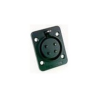
AP-6-21
Description
Loudspeaker Connectors FEMALE CHASSIS MNT
Manufacturer
Amphenol
Datasheet
1.AP-6-21.pdf
(134 pages)
Specifications of AP-6-21
Standard
EP, AP
Gender
Female
Number Of Positions / Contacts
6
Contact Plating
Tin
Color
Black
Contact Material
Brass
Voltage Rating
200 Volts
Current Rating
20 Amps
Mounting Style
Chassis (Panel)
Termination Style
Solder
Lead Free Status / Rohs Status
Lead free / RoHS Compliant


ENTERTAINMENT INTERCONNECT CATALOGUE
PRODUCT SAFETY INFORMATION
Data Sheet information contained in
individual product brochures. Failure to
observe the advice in this information
sheet and the operating conditions
specified in the Data Sheets could
result in hazardous situations.
1. Material Content and
Electrical connectors do not usually
contain hazardous materials.
They contain conducting and
non-conducting materials. Shells are
manufactured in metal and plastic.
Insulators can be formed in either
natural rubber, synthetic rubber,
plastic or glass insulating materials.
Contact materials vary with the type
of connector and its application. They
are usually manufactured from either
copper alloys, nickel, alumel, chromel
or steel. In special applications, other
alloys may be specified.
2. Fire Characteristics and
There is no fire hazard when the
connector is correctly wired and
used within the specified parameters.
Incorrect wiring or assembly of the
connector or careless use of metal
tools or conductive fluids, or transit
damage to any of the component parts
may cause electric shock or burns.
Live circuits must not be broken by
separating mated connectors as this
may cause arcing, ionisation and
burning. Heat dissipation is greater at
maximum resistance in a circuit. Hot
spots may occur when resistance is
raised locally by damage, e.g. cracked
or deformed contacts, or broken
strands of wire. Local overheating
may also result from the use of the
incorrect application tools or from
poor quality soldering.
This should be read in conjunction with
Physical Form
Electric Shock Hazard
- Amphenol Australia Pty Ltd Telephone 61 3 8796 8888 Fax 61 3 8796 8801
3. Handling
4. Disposal
5. Application
Overheating may occur if the ratings in
the Data Sheets are exceeded and can
cause breakdown of insulation and
hence electric shock.
If heating is allowed to continue
it intensifies by further increasing
the local resistance through loss of
temper or spring contact, formation of
oxide film on contacts and wires, and
leakage currents through carbonisation
of insulation and tracking points. Fire
can then result in the presence of
combustible materials and this may
release noxious fumes. Overheating
may not be visually apparent. Burns
may result from touching overheated
components.
Care must be taken to avoid damage
to any component parts of electrical
connectors during installation and
use. Although there are normally no
sharp edges, care must be taken
when handling certain components
to avoid injury to fingers. Electrical
connectors may be damaged in transit
to customers, and damage may result
in creation of hazards. Products
should therefore be examined prior to
installation/use and rejected if found to
be damaged.
Incineration of certain materials may
release noxious or even toxic fumes.
Connectors with exposed contacts
should not be selected for use on the
current supply side of an electrical
circuit, because an electric shock
could result from touching exposed
contacts of an unmated connector.
Voltages in excess of 30 V.A.C. or 42.5
Important General Information
V.D.C. are potentially hazardous and
care should be taken to ensure that
such voltages cannot be transmitted
in any way to exposed metal parts of
the connector body. The connector
and wiring should be checked, before
making live, to have no damage to
metal parts or insulators, no solder
blobs, loose strands, conducting
lubricants, swarf, or any other
undesired conducting particles.
Circuit resistance and continuity check
should be made to make certain that
there are no low resistance joints or
spurious conducting paths. Always
use the correct application tools as
specified in the Data Sheets. Do not
permit untrained personnel to wire,
assemble or tamper with connectors.
For operation voltage please see
appropriate national regulations.
A) Air and creepage paths /
The admissible operating voltages
depend on the individual applications
and the valid national and other
applicable safety regulations. For this
reason the air and creepage path data
are only reference values. Observe
reduction of air and creepage paths
due to PC board and/or harnessing.
B) Other important information
Amphenol Australia Pty Ltd
continuously endeavours to improve
its products. Therefore, products
may deviate from the description,
technical data and shape as shown
in product brochures.
C) Assembly instructions
If applicable, special assembly
instructions have been included
in or on the connector packaging.
See also separate instructions in
product brochures.
Operating voltage.
AC SERIES CABLE CONNECTORS
PRODUCT SAFETY INFORMATION
www.amphenolaudio.com
134
Related parts for AP-6-21
Image
Part Number
Description
Manufacturer
Datasheet
Request
R

Part Number:
Description:
Loudspeaker Connectors MALE CHASSIS MOUNT
Manufacturer:
Amphenol
Datasheet:

Part Number:
Description:
Loudspeaker Connectors FEMALE CHASSIS MOUNT
Manufacturer:
Amphenol
Datasheet:

Part Number:
Description:
Loudspeaker Connectors FEMALE CHASSIS MOUNT
Manufacturer:
Amphenol
Datasheet:

Part Number:
Description:
Loudspeaker Connectors FEM CHASIS Round FLNG Machined CONT
Manufacturer:
Amphenol
Datasheet:
Part Number:
Description:
Loudspeaker Connectors ML CHASIS Round FLNG Machined CONT
Manufacturer:
Amphenol
Datasheet:
Part Number:
Description:
Cable Specification: PU CABLE, UL20549 24AWG*8C+AD,OD= 6.0mm
Manufacturer:
Amphenol