AP-6-21 Amphenol, AP-6-21 Datasheet - Page 19
AP-6-21
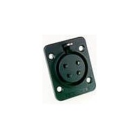
Manufacturer Part Number
AP-6-21
Description
Loudspeaker Connectors FEMALE CHASSIS MNT
Manufacturer
Amphenol
Datasheet
1.AP-6-21.pdf
(134 pages)
Specifications of AP-6-21
Standard
EP, AP
Gender
Female
Number Of Positions / Contacts
6
Contact Plating
Tin
Color
Black
Contact Material
Brass
Voltage Rating
200 Volts
Current Rating
20 Amps
Mounting Style
Chassis (Panel)
Termination Style
Solder
Lead Free Status / Rohs Status
Lead free / RoHS Compliant


ENTERTAINMENT INTERCONNECT CATALOGUE
Push the cable through the boot assembly
and strip the cable back 35 to 40 mm.
Twist the shield wire.
Fit the cable into the ‘Jaws’ cable clamp
ensuring that the cable is pushed up to the
neck of the clamp within 3mm.
Pull back the conductors into their individual
wire guidetracks. Note: Two spring fingers in
the clamp will hold the conductors in position
during subsequent operations. The ends of the
two insulated wires must be on or past the
minimum wire length mark.
35
40
3
1
2
3
- Amphenol Australia Pty Ltd Telephone 61 3 8796 8888 Fax 61 3 8796 8801
For ground protection the twisted shield wire
is clipped in place with the ground protect flap.
Trim back the shield wire, so there are no
wires coming out of the flap and fit the ‘Jaws’
cable clamp into the shell assembly, ensuring
the keyways are aligned.
4
5
AC IDC
SERIES CABLE
ASSEMBLY
INSTRUCTIONS
Close the cable clamp slightly and push the
boot over the clamp ensuring the wires fit inside
the boot.
Final assembly can be achieved either by
manually screwing the boot on, or by using an
Amphenol Australia T2860 termination tool.
IDC ASSEMBLY INSTRUCTIONS
AC SERIES XLR CABLE CONNECTORS
www.amphenolaudio.com
6
7
19
Related parts for AP-6-21
Image
Part Number
Description
Manufacturer
Datasheet
Request
R

Part Number:
Description:
Loudspeaker Connectors MALE CHASSIS MOUNT
Manufacturer:
Amphenol
Datasheet:

Part Number:
Description:
Loudspeaker Connectors FEMALE CHASSIS MOUNT
Manufacturer:
Amphenol
Datasheet:

Part Number:
Description:
Loudspeaker Connectors FEMALE CHASSIS MOUNT
Manufacturer:
Amphenol
Datasheet:

Part Number:
Description:
Loudspeaker Connectors FEM CHASIS Round FLNG Machined CONT
Manufacturer:
Amphenol
Datasheet:
Part Number:
Description:
Loudspeaker Connectors ML CHASIS Round FLNG Machined CONT
Manufacturer:
Amphenol
Datasheet:
Part Number:
Description:
Cable Specification: PU CABLE, UL20549 24AWG*8C+AD,OD= 6.0mm
Manufacturer:
Amphenol