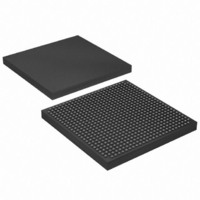
EP1S25F672C8 Altera, EP1S25F672C8 Datasheet - Page 9

EP1S25F672C8
Manufacturer Part Number
EP1S25F672C8
Description
IC STRATIX FPGA 25K LE 672-FBGA
Manufacturer
Altera
Series
Stratix®r
Datasheet
1.EP1S10F780C7.pdf
(276 pages)
Specifications of EP1S25F672C8
Number Of Logic Elements/cells
25660
Number Of Labs/clbs
2566
Total Ram Bits
1944576
Number Of I /o
473
Voltage - Supply
1.425 V ~ 1.575 V
Mounting Type
Surface Mount
Operating Temperature
0°C ~ 85°C
Package / Case
672-FBGA
Lead Free Status / RoHS Status
Contains lead / RoHS non-compliant
Number Of Gates
-
Other names
544-1119
Available stocks
Company
Part Number
Manufacturer
Quantity
Price
Company:
Part Number:
EP1S25F672C8
Manufacturer:
AD
Quantity:
2 562
Company:
Part Number:
EP1S25F672C8
Manufacturer:
ALTERA
Quantity:
3 000
Part Number:
EP1S25F672C8
Manufacturer:
ALTERA
Quantity:
20 000
Company:
Part Number:
EP1S25F672C8N
Manufacturer:
ALTERA
Quantity:
465
Part Number:
EP1S25F672C8N
Manufacturer:
ALTERA/阿尔特拉
Quantity:
20 000
Introduction
Altera Corporation
July 2005
S51001-3.2
The Stratix
SRAM process, with densities of up to 79,040 logic elements (LEs) and up
to 7.5 Mbits of RAM. Stratix devices offer up to 22 digital signal
processing (DSP) blocks with up to 176 (9-bit × 9-bit) embedded
multipliers, optimized for DSP applications that enable efficient
implementation of high-performance filters and multipliers. Stratix
devices support various I/O standards and also offer a complete clock
management solution with its hierarchical clock structure with up to
420-MHz performance and up to 12 phase-locked loops (PLLs).
The following shows the main sections in the Stratix Device Family Data
Sheet:
Section
Features . . . . . . . . . . . . . . . . . . . . . . . . . . . . . . . . . . . . . . . . . . . . . 1–2
Functional Description . . . . . . . . . . . . . . . . . . . . . . . . . . . . . . . . 2–1
Logic Array Blocks. . . . . . . . . . . . . . . . . . . . . . . . . . . . . . . . . . . . 2–3
Logic Elements . . . . . . . . . . . . . . . . . . . . . . . . . . . . . . . . . . . . . . . 2–6
MultiTrack Interconnect . . . . . . . . . . . . . . . . . . . . . . . . . . . . . . 2–14
TriMatrix Memory . . . . . . . . . . . . . . . . . . . . . . . . . . . . . . . . . . . 2–21
Digital Signal Processing Block . . . . . . . . . . . . . . . . . . . . . . . . 2–52
PLLs & Clock Networks . . . . . . . . . . . . . . . . . . . . . . . . . . . . . . 2–73
I/O Structure . . . . . . . . . . . . . . . . . . . . . . . . . . . . . . . . . . . . . . 2–104
High-Speed Differential I/O Support. . . . . . . . . . . . . . . . . . 2–130
Power Sequencing & Hot Socketing . . . . . . . . . . . . . . . . . . . 2–140
IEEE Std. 1149.1 (JTAG) Boundary-Scan Support. . . . . . . . . . 3–1
SignalTap II Embedded Logic Analyzer . . . . . . . . . . . . . . . . . 3–5
Configuration . . . . . . . . . . . . . . . . . . . . . . . . . . . . . . . . . . . . . . . . 3–5
Temperature Sensing Diode. . . . . . . . . . . . . . . . . . . . . . . . . . . 3–13
Operating Conditions . . . . . . . . . . . . . . . . . . . . . . . . . . . . . . . . . 4–1
Power Consumption . . . . . . . . . . . . . . . . . . . . . . . . . . . . . . . . . 4–17
Timing Model . . . . . . . . . . . . . . . . . . . . . . . . . . . . . . . . . . . . . . . 4–19
Software. . . . . . . . . . . . . . . . . . . . . . . . . . . . . . . . . . . . . . . . . . . . . 5–1
Device Pin-Outs . . . . . . . . . . . . . . . . . . . . . . . . . . . . . . . . . . . . . . 5–1
Ordering Information . . . . . . . . . . . . . . . . . . . . . . . . . . . . . . . . . 5–1
®
family of FPGAs is based on a 1.5-V, 0.13-µm, all-layer copper
1. Introduction
Page
1–1


