20-101-0404 Rabbit Semiconductor, 20-101-0404 Datasheet - Page 25
20-101-0404
Manufacturer Part Number
20-101-0404
Description
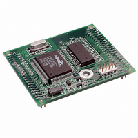
MODULE RABBITCORE RCM2000
Manufacturer
Rabbit Semiconductor
Datasheet
1.20-101-0383.pdf
(80 pages)
Specifications of 20-101-0404
Module/board Type
MPU Core Module
Product
Microcontroller Modules
Core Processor
Rabbit 2000
Clock Speed
25.8 MHz
Interface Type
Ethernet, Serial
Flash
256 KB
Timers
5 x 8 bit, 2 x 10 bit
Operating Supply Voltage
4.75 V to 5.25 V
Board Size
48.3 mm x 58.4 mm x 14 mm
Core
RCM2000
Processor Series
RCM2000
Cpu Core
Rabbit 2000
For Use With/related Products
RCM2000
Lead Free Status / RoHS Status
Lead free / RoHS Compliant
Other names
316-1083


3.1.3 Serial Communication
The following sample programs can be found in the
Two sample programs,
CONTROL.C
are available to illustrate RS-232
communication. To run these sample
programs, you will have to add an
RS-232 transceiver such as the
MAX232 at location U2 and four
100 nF charge-storage capacitors at
C3–C6 on the Prototyping Board.
Also install the 2 × 5 IDC header
included with the Prototyping Board
accessory parts at J6 to interface the
RS-232 signals.
The diagram shows the connections.
•
•
User’s Manual
CORE_FLOWCONTROL.C
program demonstrates hardware flow control by configuring Serial Port C (PC3/PC2)
for CTS/RTS with serial data coming from TxB at 115,200 bps. One character at a time
is received and is displayed in the
To set up the Prototyping Board, you will need to tie PC4 and PC5
(TxB and RxB) together at header J4, and you will also tie PC2 and
PC3 (TxC and RxC) together as shown in the diagram.
A repeating triangular pattern should print out in the
The program will periodically switch flow control on or off to demon-
strate the effect of no flow control.
Refer to the
ence Manual for a general description on how to set up flow control lines.
CORE_PARITY.C
sending byte values 0–127 from Serial Port B to Serial Port C. The program will switch
between generating parity or not on Serial Port B. Serial Port C will always be checking
parity, so parity errors should occur during every other sequence.
To set up the Prototyping Board, you will need to tie PC4 and PC3
(TxB and RxC) together at header J4 as shown in the diagram.
The Dynamic C
and
serBflowcontrolOn()
CORE_PARITY.C
STDIO
—This program demonstrates the use of parity modes by repeatedly
CORE_FLOW-
window will display the error sequence.
—This
,
STDIO
function call in the Dynamic C Function Refer-
window.
SAMPLES\RCM2000
STDIO
window.
folder.
GND
GND
21
Related parts for 20-101-0404
Image
Part Number
Description
Manufacturer
Datasheet
Request
R

Part Number:
Description:
COMPUTER SGL-BRD BL2500 29.4MHZ
Manufacturer:
Rabbit Semiconductor
Datasheet:

Part Number:
Description:
COMPUTER SGL-BRD BL2500 29.4MHZ
Manufacturer:
Rabbit Semiconductor
Datasheet:

Part Number:
Description:
DISPLAY GRAPHIC 12KEY PROG OP670
Manufacturer:
Rabbit Semiconductor
Datasheet:
Part Number:
Description:
DISPLAY GRAPHIC 12KEY ETH OP6700
Manufacturer:
Rabbit Semiconductor
Datasheet:

Part Number:
Description:
COMPUTER SINGLE-BOARD BL2030
Manufacturer:
Rabbit Semiconductor
Part Number:
Description:
COMPUTER SGL-BOARD ETH BL2010
Manufacturer:
Rabbit Semiconductor

Part Number:
Description:
MODULE OP6810 W/O ETH/MEM EXPANS
Manufacturer:
Rabbit Semiconductor
Datasheet:
Part Number:
Description:
COMPUTER SINGLE-BOARD BL2020
Manufacturer:
Rabbit Semiconductor
Part Number:
Description:
COMPUTER BL2010 W/FRICTION LOCK
Manufacturer:
Rabbit Semiconductor
Part Number:
Description:
COMPUTER BL2020 W/FRICTION LOCK
Manufacturer:
Rabbit Semiconductor
Part Number:
Description:
COMPUTER SGL-BRD BL2500 44.2MHZ
Manufacturer:
Rabbit Semiconductor
Datasheet:
Part Number:
Description:
COMPUTER SGL-BOARD FULL BL2000
Manufacturer:
Rabbit Semiconductor

Part Number:
Description:
COMPUTER SINGLE-BOARD BL2110
Manufacturer:
Rabbit Semiconductor

Part Number:
Description:
COMPUTER SGL-BRD 29.4MHZ BL2610
Manufacturer:
Rabbit Semiconductor
Datasheet:
Part Number:
Description:
INTERFACE OP6800 512K FLASH&SRAM
Manufacturer:
Rabbit Semiconductor
Datasheet: