20-101-0673 Rabbit Semiconductor, 20-101-0673 Datasheet - Page 4
20-101-0673
Manufacturer Part Number
20-101-0673
Description
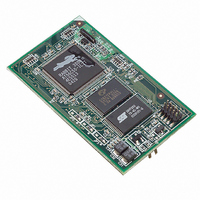
MODULE RABBITCORE RCM3610
Manufacturer
Rabbit Semiconductor
Datasheet
1.20-101-0673.pdf
(136 pages)
Specifications of 20-101-0673
Module/board Type
MPU Core Module
Product
Microcontroller Modules
Core Processor
Rabbit 3000
Clock Speed
22.1 MHz
Interface Type
Serial
Flash
256 KB
Timers
10 x 8 bit, 1 x 10 bit
Operating Supply Voltage
3 V to 3.6 V
Board Size
31 mm x 54 mm x 16 mm
Core
RCM3610
Processor Series
RCM3600
For Use With/related Products
RCM3610
Lead Free Status / RoHS Status
Lead free / RoHS Compliant
Other names
316-1103


Chapter 5. Software Reference
Appendix A. RCM3600 Specifications
Appendix B. Prototyping Board
Appendix C. LCD/Keypad Module
5.1 More About Dynamic C ..................................................................................................................... 33
5.2 Dynamic C Functions......................................................................................................................... 35
5.3 Upgrading Dynamic C ....................................................................................................................... 54
A.1 Electrical and Mechanical Characteristics ........................................................................................ 56
A.2 Bus Loading ...................................................................................................................................... 60
A.3 Rabbit 3000 DC Characteristics ........................................................................................................ 63
A.4 I/O Buffer Sourcing and Sinking Limit............................................................................................. 64
A.5 Conformal Coating ............................................................................................................................ 65
A.6 Jumper Configurations ...................................................................................................................... 66
B.1 Introduction ....................................................................................................................................... 68
B.2 Mechanical Dimensions and Layout ................................................................................................. 71
B.3 Power Supply..................................................................................................................................... 72
B.4 Using the Prototyping Board ............................................................................................................. 73
B.5 RCM3600 Prototyping Board Jumper Configurations...................................................................... 84
C.1 Specifications..................................................................................................................................... 87
C.2 Contrast Adjustments for All Boards ................................................................................................ 89
C.3 Keypad Labeling................................................................................................................................ 90
C.4 Header Pinouts................................................................................................................................... 91
C.5 Install Connectors on Prototyping Board .......................................................................................... 92
C.6 Mounting LCD/Keypad Module on the Prototyping Board.............................................................. 93
C.7 Bezel-Mount Installation ................................................................................................................... 94
C.8 Sample Programs............................................................................................................................... 97
C.9 LCD/Keypad Module Function Calls................................................................................................ 98
5.2.1 Board Initialization ..................................................................................................................... 35
5.2.2 Analog Inputs ............................................................................................................................. 36
5.2.3 Digital I/O................................................................................................................................... 52
5.2.4 Serial Communication Drivers ................................................................................................... 53
5.3.1 Add-On Modules ........................................................................................................................ 54
A.1.1 Headers ...................................................................................................................................... 59
B.1.1 Prototyping Board Features ....................................................................................................... 69
B.4.1 Adding Other Components ........................................................................................................ 74
B.4.2 Analog Features ......................................................................................................................... 75
B.4.3 Serial Communication ............................................................................................................... 80
B.4.4 Other Prototyping Board Modules............................................................................................. 83
C.4.1 I/O Address Assignments .......................................................................................................... 91
C.7.1 Connect the LCD/Keypad Module to Your Prototyping Board ................................................ 96
C.9.1 LCD/Keypad Module Initialization ........................................................................................... 98
C.9.2 LEDs .......................................................................................................................................... 98
C.9.3 LCD Display .............................................................................................................................. 99
C.9.4 Keypad ..................................................................................................................................... 119
B.4.2.1 A/D Converter Inputs........................................................................................................ 75
B.4.2.2 Thermistor Input ............................................................................................................... 77
B.4.2.3 Other A/D Converter Features .......................................................................................... 78
B.4.2.4 A/D Converter Calibration................................................................................................ 79
B.4.3.1 RS-232 .............................................................................................................................. 81
B.4.3.2 RS-485 .............................................................................................................................. 82
RabbitCore RCM3600
33
55
67
87
Related parts for 20-101-0673
Image
Part Number
Description
Manufacturer
Datasheet
Request
R

Part Number:
Description:
COMPUTER SGL-BRD BL2500 29.4MHZ
Manufacturer:
Rabbit Semiconductor
Datasheet:

Part Number:
Description:
COMPUTER SGL-BRD BL2500 29.4MHZ
Manufacturer:
Rabbit Semiconductor
Datasheet:

Part Number:
Description:
DISPLAY GRAPHIC 12KEY PROG OP670
Manufacturer:
Rabbit Semiconductor
Datasheet:
Part Number:
Description:
DISPLAY GRAPHIC 12KEY ETH OP6700
Manufacturer:
Rabbit Semiconductor
Datasheet:

Part Number:
Description:
COMPUTER SINGLE-BOARD BL2030
Manufacturer:
Rabbit Semiconductor
Part Number:
Description:
COMPUTER SGL-BOARD ETH BL2010
Manufacturer:
Rabbit Semiconductor

Part Number:
Description:
MODULE OP6810 W/O ETH/MEM EXPANS
Manufacturer:
Rabbit Semiconductor
Datasheet:
Part Number:
Description:
COMPUTER SINGLE-BOARD BL2020
Manufacturer:
Rabbit Semiconductor
Part Number:
Description:
COMPUTER BL2010 W/FRICTION LOCK
Manufacturer:
Rabbit Semiconductor
Part Number:
Description:
COMPUTER BL2020 W/FRICTION LOCK
Manufacturer:
Rabbit Semiconductor
Part Number:
Description:
COMPUTER SGL-BRD BL2500 44.2MHZ
Manufacturer:
Rabbit Semiconductor
Datasheet:
Part Number:
Description:
COMPUTER SGL-BOARD FULL BL2000
Manufacturer:
Rabbit Semiconductor

Part Number:
Description:
COMPUTER SINGLE-BOARD BL2110
Manufacturer:
Rabbit Semiconductor

Part Number:
Description:
COMPUTER SGL-BRD 29.4MHZ BL2610
Manufacturer:
Rabbit Semiconductor
Datasheet:
Part Number:
Description:
INTERFACE OP6800 512K FLASH&SRAM
Manufacturer:
Rabbit Semiconductor
Datasheet: