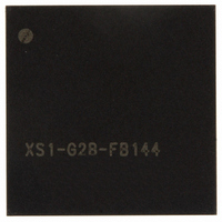
XS1-G02B-FB144-C4 XMOS, XS1-G02B-FB144-C4 Datasheet - Page 9

XS1-G02B-FB144-C4
Manufacturer Part Number
XS1-G02B-FB144-C4
Description
IC MPU 32BIT DUAL CORE 144FBGA
Manufacturer
XMOS
Datasheet
1.XS1-G02B-FB144-C4.pdf
(22 pages)
Specifications of XS1-G02B-FB144-C4
Processor Type
XCore 32-Bit
Speed
800MIPS
Voltage
0.95 V ~ 1.05 V
Mounting Type
Surface Mount
Package / Case
144-BGA
Lead Free Status / RoHS Status
Lead free / RoHS Compliant
Features
-
Other names
880-1006
Available stocks
Company
Part Number
Manufacturer
Quantity
Price
XS1-G2 144BGA Datasheet (2.6)
Functional description
SS_XC0_BS0 Boot status pin
SS_DEBUG This pin is used to synchronize the debugging of multiple G2 devices.
SS_RESET Active low asynchronous-assertion reset signal. At power-up, this pin
SS_XC0_CFG0 Reserved, tie pin to IO_VDD
SS_TEST_ENA Reserved, tie pin to ground.
The boot status pin is dual function.
SS_XC0_BS0 functions as an input prior to the de-assertion of reset. The XS1-
G2 latches the value driven onto this pin on the rising edge (de-assertion) of
SS_RESET. The value driven should be static and configured using a pullup or
pulldown resistor, as the XS1-G2 drives the boot status on this pin after reset.
The value configured on this pin defines the boot mode for core 0 as follows:
NOTE: If secure boot from OTP is enabled by programming the OTP, the boot
mode indicated on the SS_XC0_BS0 pin is ignored.
After reset is complete, SS_XC0_BS0 becomes an output and the value on this
pin indicates the XCore0 boot mode:
SS_XC0_BS0 should be tied to IO_VDD.
For further details on booting XCores see the XS1-G System Specification
document (http://xmos.com/published/xsystem).
This pin can operate in both output and input mode. In output mode and when
configured to do so, SS_DEBUG is driven low by the device when one or more
internal XCore processors hit a debug break point. Prior to this point the pin is
tri-stated. In input mode and when configured to do so, driving this pin low
puts all internal CPUs into debug mode. Software can set the behavior of each
internal XCore based on this pin. This pin should have an external pull up to
IO_VDD(3.3V) of 4K7 ohms.
must be activated for at least 5us after the power supplies are stable to ensure
reliable boot up. Following a reset the PLL re-establishes lock after which the
XCores boot up according to the BOOT_MODE (see SS_XC0_BS1, SS_XC0_BS0).
Value
0
1
Value
0
1
www.xmos.com
Description
Boot from SPI
Boot from JTAG
Description
Boot from SPI
Boot from OTP or JTAG
9/22


