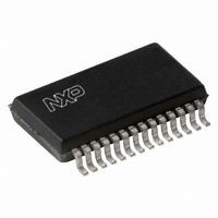
UDA1344TS/N2,518 NXP Semiconductors, UDA1344TS/N2,518 Datasheet - Page 9

UDA1344TS/N2,518
Manufacturer Part Number
UDA1344TS/N2,518
Description
IC STEREO AUDIO CODEC 28SSOP
Manufacturer
NXP Semiconductors
Type
Stereo Audior
Datasheet
1.UDA1344TSN2512.pdf
(27 pages)
Specifications of UDA1344TS/N2,518
Package / Case
28-SSOP (0.200", 5.30mm Width)
Data Interface
Serial
Resolution (bits)
20 b
Number Of Adcs / Dacs
2 / 2
Sigma Delta
Yes
S/n Ratio, Adcs / Dacs (db) Typ
95 / 100
Voltage - Supply, Analog
2.7 V ~ 3.6 V
Voltage - Supply, Digital
2.7 V ~ 3.6 V
Operating Temperature
-40°C ~ 85°C
Mounting Type
Surface Mount
Number Of Adc Inputs
2
Number Of Dac Outputs
2
Conversion Rate
55 KSPS
Interface Type
Serial (I2S)
Resolution
20 bit
Maximum Operating Temperature
+ 85 C
Mounting Style
SMD/SMT
Minimum Operating Temperature
- 40 C
Number Of Channels
2 ADC / 2 DAC
Lead Free Status / RoHS Status
Lead free / RoHS Compliant
Lead Free Status / RoHS Status
Lead free / RoHS Compliant, Lead free / RoHS Compliant
Other names
935261790518
UDA1344TSDB-T
UDA1344TSDB-T
UDA1344TSDB-T
UDA1344TSDB-T
NXP Semiconductors
Static pin mode
The UDA1344TS is set to static pin mode by setting both
pins MC1 and MC2 to HIGH level.
The controllable features in this mode are:
• System clock frequency selection
• Data input/output format selection
• De-emphasis and mute control
• Power-down and ADC input level selection.
P
The pinning definition in the static pin mode is given in
Table 6.
Table 6 Pinning definition in static pin model
S
In the static pin mode the options are 256f
given in Table 7.
Table 7 System clock selection
2001 Jun 29
INNING DEFINITION
YSTEM CLOCK
Low-voltage low-power stereo audio
CODEC with DSP features
PIN MP3
MP1
MP2
MP3
MP4
MP5
PIN
HIGH
LOW
data input/output setting
three-level pin to select no
de-emphasis, de-emphasis or mute
256f
three-level pin to select
ADC power-down, ADC input
1 V (RMS) or ADC input 2 V (RMS)
data input/output setting
256f
384f
s
or 384f
s
s
clock frequency
clock frequency
DESCRIPTION
s
SELECTION
system clock selection
s
and 384f
s
as
9
M
The level definition of pin MP2 pin is given in Table 8.
Table 8 Levels for pin MP2
I
The input/output data format can be selected using
pins MP1 and MP5 as given in Table 9.
Table 9 Data format selection
ADC
In the static pin mode the three-level pin MP4 is used to
select 0 or 6 dB gain and power-down.
Table 10 Levels for pin MP4
NPUT
PIN MP1 PIN MP5
UTE AND DE
HIGH
HIGH
LOW
LOW
INPUT VOLTAGE SELECTION AND POWER
/
OUTPUT DATA FORMAT SELECTION
PIN MP2
PIN MP4
0.5V
0.5V
HIGH
HIGH
LOW
LOW
DDD
DDD
-
HIGH
HIGH
EMPHASIS
LOW
LOW
no de-emphasis and mute
de-emphasis 44.1 kHz
mute
input: MSB-justified
input: I
input: LSB-justified 20 bits;
output: MSB-justified
input: LSB-justified 16 bits;
output: MSB-justified
ADC power-down
6 dB gain
0 dB gain
2
S-bus
SELECTION
SELECTION
SELECTION
UDA1344TS
Product specification
-
DOWN


