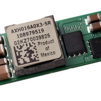
AXA010A0G93-SRZ Lineage Power, AXA010A0G93-SRZ Datasheet - Page 14

AXA010A0G93-SRZ
Manufacturer Part Number
AXA010A0G93-SRZ
Description
DC/DC Converters & Regulators 2.5Vout 10A SMT 10-14Vin
Manufacturer
Lineage Power
Series
AXA010r
Datasheet
1.108970013.pdf
(20 pages)
Specifications of AXA010A0G93-SRZ
Product
Non-Isolated / POL
Output Power
25 W
Input Voltage Range
10 V to 14 V
Number Of Outputs
1
Output Voltage (channel 1)
2.5 V
Output Current (channel 1)
10 A
Package / Case Size
SMD
Output Type
Non-Isolated
Output Voltage
2.5 V
Package / Case
SMD
Lead Free Status / Rohs Status
Lead free / RoHS Compliant
Other names
CC109102860
Data Sheet
March 14, 2006
Thermal Considerations
Power modules operate in a variety of thermal
environments; however, sufficient cooling should always
be provided to help ensure reliable operation.
Considerations include ambient temperature, airflow,
module power dissipation, and the need for increased
reliability. A reduction in the operating temperature of the
module will result in an increase in reliability. The thermal
data presented here is based on physical measurements
taken in a wind tunnel. The test set-up is shown in Figure
32. Note that the airflow is parallel to the short axis of the
module as shown in figure 31. The derating data applies
to airflow in either direction of the module’s short axis.
Figure 31. T ref Temperature measurement location.
The thermal reference point, T
specifications is shown in Figure 31. For reliable
operation this temperature should not exceed 115
The output power of the module should not exceed the
rated power of the module (Vo,set x Io,max).
Please refer to the Application Note “Thermal
Characterization Process For Open-Frame Board-
Mounted Power Modules” for a detailed discussion of
thermal aspects including maximum device temperatures.
LINEAGE
Top View
POWER
ref
used in the
Air Flow
10 – 14Vdc input; 1.2Vdc to 5.5Vdc Output; 10A output current
T
ref
Austin Lynx
o
C.
Wind T unnel
Heat Transfer via Convection
Increased airflow over the module enhances the heat
transfer via convection. Thermal derating curves showing
the maximum output current that can be delivered at
different local ambient temperatures (T
conditions ranging from natural convection and up to
2m/s (400 ft./min) are shown in the Characteristics
Curves section.
Layout Considerations
Copper paths must not be routed beneath the power
module. For additional layout guide-lines, refer to the
FLTR100V10 application note.
Figure 32. Thermal Test Set-up.
TM
12 V SMT Non-isolated Power Modules:
PWBs
flow
Air
(0.325)
x
8.3_
(3.0)
76.2_
25.4_
(1.0)
A
) for airflow
Probe Loc ation
for measuring
airflow and
ambient
temperature
Power Module
14


