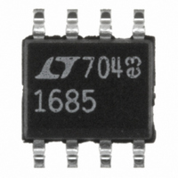
LTC1685CS8#PBF Linear Technology, LTC1685CS8#PBF Datasheet - Page 3

LTC1685CS8#PBF
Manufacturer Part Number
LTC1685CS8#PBF
Description
IC TXRX RS485 PREC DELAY 8-SOIC
Manufacturer
Linear Technology
Type
Transceiverr
Datasheet
1.LTC1685CS8PBF.pdf
(12 pages)
Specifications of LTC1685CS8#PBF
Number Of Drivers/receivers
1/1
Protocol
RS422, RS485
Voltage - Supply
4.75 V ~ 5.25 V
Mounting Type
Surface Mount
Package / Case
8-SOIC (3.9mm Width)
Lead Free Status / RoHS Status
Lead free / RoHS Compliant
Available stocks
Company
Part Number
Manufacturer
Quantity
Price
DC ELECTRICAL CHARACTERISTICS
SWITCHING CHARACTERISTICS
temperature range, otherwise specifications are at T
SYMBOL
I
I
R
C
Fail-Safe Time Time to Detect Fail-Safe Condition
CMRR
C
SYMBOL
t
t
t
t
t
t
t
t
t
t
t
t
t
t
temperature range, otherwise specifications are at T
OSD2
OSR
PLH
SKEW
r
ZH
ZL
LZ
PLH
SQD
ZL
ZH
LZ
PKG-PKG
HZ
HZ
IN
LOAD
, t
IN
f
, t
, t
PHL
PHL
PARAMETER
Driver Input-to-Output
Propagation Delay
Driver Output A-to-Output
B Skew
Driver Rise/Fall Time
Driver Enable to Output High
Driver Enable to Output Low
Driver Disable from Low
Driver Disable from High
Receiver Input-to-Output
Propagation Delay
Receiver Skew t
Receiver Enable to Output Low
Receiver Enable to Output High C
Receiver Disable from Low
Receiver Disable from High
Maximum Receiver Input
Rise/Fall Times
Package-to-Package Skew
Minimum Input Pulse Width
Maximum Data Rate
Maximum Input Frequency
PARAMETER
Driver Short-Circuit Current, V
Receiver Short-Circuit Current
Input Resistance
Input Capacitance
Open-Circuit Input Voltage, Figure 5
Receiver Input Common Mode Rejection Ratio
Receiver and Driver Output Load Capacitance
U
PLH
– t
PHL
OUT
R
LTC1685C
LTC1685I
R
Figures 3, 5
R
Figures 3, 5
C
C
C
C
C
LTC1685C
LTC1685I
C
C
C
C
(Note 4)
Same Temperature (Note 4)
V
LTC1685C
LTC1685I
V
LTC1685C
LTC1685I
V
LTC1685C
LTC1685I
DIFF
DIFF
DIFF
L
L
L
L
L
L
L
L
L
L
DD
DD
DD
= 15pF, Figures 3, 7
= 100pF, S2 Closed, Figures 4, 6
= 100pF, S1 Closed, Figures 4, 6
= 15pF, S1 Closed, Figures 4, 6
= 15pF, S2 Closed, Figures 4, 6
= 15pF, Figures 3, 7
= 15pF, S1 Closed, Figures 2, 8
= 15pF, S2 Closed, Figures 2, 8
= 15pF, S1 Closed, Figures 2, 8
= 15pF, S2 Closed, Figures 2, 8
= LOW
= 5V 5% (Note 4)
= 5V 5% (Note 4)
= 5V 5% (Note 4)
= 54 , C
= 54 , C
= 54 , C
CONDITIONS
A
A
L1
L1
L1
= 25 C. V
= 25 C. V
= C
= C
= C
The
L2
L2
L2
CONDITIONS
V
V
– 7V V
A, B Inputs, D, DE, RE
V
V
(Note 4)
OUT
OUT
DD
CM
= 100pF, Figures 3, 5,
= 100pF,
= 100pF,
= 5V (Note 4)
= 2.6V, f = 26MHz
= – 7V or 10V (Note 5)
= 0V or V
DD
DD
denotes the specifications which apply over the full operating
The
CM
= 5V, unless otherwise noted. (Notes 2, 3)
= 5V 5%, unless otherwise noted. (Notes 2, 3)
12V
denotes the specifications which apply over the full operating
DD
(Note 5)
MIN
MIN
3.2
22
15
13
15
13
52
40
26
20
18.5
18.5
18.5
18.5
TYP
TYP
500
500
3.3
3.5
1.5
45
25
25
25
25
25
25
25
25
17
20
60
50
30
25
3
2
2000
LTC1685
MAX
MAX
19.2
500
3.4
20
20
22
25
50
50
50
50
22
25
50
50
50
50
25
UNITS
UNITS
Mbps
Mbps
3
MHz
MHz
mA
mA
k
dB
pF
pF
ns
ns
ps
ns
ns
ns
ns
ns
ns
ns
ps
ns
ns
ns
ns
ns
ns
ns
ns
V
s


