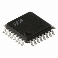
TDA8020HL/C2,118 NXP Semiconductors, TDA8020HL/C2,118 Datasheet - Page 10

TDA8020HL/C2,118
Manufacturer Part Number
TDA8020HL/C2,118
Description
IC SMART CARD INTERFACE 32LQFP
Manufacturer
NXP Semiconductors
Type
Interfacer
Datasheet
1.TDA8020HLC2118.pdf
(28 pages)
Specifications of TDA8020HL/C2,118
Package / Case
32-LQFP
Voltage - Supply
2.7 V ~ 6.5 V
Mounting Type
Surface Mount
Maximum Operating Temperature
+ 85 C
Minimum Operating Temperature
- 40 C
Mounting Style
SMD/SMT
Lead Free Status / RoHS Status
Lead free / RoHS Compliant
Number Of Drivers/receivers
-
Protocol
-
Lead Free Status / Rohs Status
Lead free / RoHS Compliant
Other names
568-3522-2
935272983118
TDA8020HL2BD-T
935272983118
TDA8020HL2BD-T
Available stocks
Company
Part Number
Manufacturer
Quantity
Price
Company:
Part Number:
TDA8020HL/C2,118
Manufacturer:
NXP Semiconductors
Quantity:
10 000
Part Number:
TDA8020HL/C2,118
Manufacturer:
NXP/恩智浦
Quantity:
20 000
Philips Semiconductors
W
The write sequence is as follows:
1. START condition
2. Byte 1: ADDRESS plus write command
3. ACK: acknowledge
4. Byte 2: CONTROL byte; see Table 3
5. ACK: acknowledge
6. STOP condition.
Table 3 CONTROL byte bits (all bits cleared after power-on)
All frequency changes are synchronous, thus ensuring that no pulse is shorter than 45% of the smallest period. For cards
power reduction modes, CLKIN may be stopped after switching to stop LOW or stop HIGH. CLKIN should be restarted
before leaving this mode and the selected frequency must not be changed during a CLK stop mode.
A correct duty factor can not be guaranteed in the CLKIN configuration, as it depends on the duty factor of the CLKIN
signal.
2003 Nov 06
BIT
0
1
2
3
4
5
6
7
RITE SEQUENCE
Dual IC card interface
START/STOP when set, initiates an activation and a cold reset procedure; when reset, initiates a deactivation
WARM
3 V / 5 V
PDOWN
CLKPD
CLKSEL1
CLKSEL2
I/OEN
NAME
sequence
when set, initiates a warm reset procedure; automatically reset by hardware when the card starts
answering or when the card is declared mute (once the status has been read)
when set; V
when set, the configuration defined by bit CLKPD is applied to pin CLK, and the circuit enters the
Power-down mode; when reset, the circuit goes back to normal (active) mode
when set, CLK is stopped HIGH during Power-down mode; when reset, CLK is stopped LOW in
Power-down mode
determine the clock to the card in active mode:
when set, I/O data is transferred on pin I/OuC; when reset, pin I/OuC is high-impedance
00: CLKIN/8
01: CLKIN/4
10: CLKIN/2
11: CLKIN
CC
= 3 V; when reset; V
CC
10
= 5 V
DESCRIPTION
TDA8020HL
Product specification


