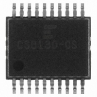
CS8130-CS Cirrus Logic Inc, CS8130-CS Datasheet - Page 10

CS8130-CS
Manufacturer Part Number
CS8130-CS
Description
IC IR TRANSCEIVER 2-5V 20-SSOP
Manufacturer
Cirrus Logic Inc
Type
Transceiverr
Datasheet
1.CS8130-CS.pdf
(28 pages)
Specifications of CS8130-CS
Mounting Type
Surface Mount
Voltage - Supply
2.7 V ~ 5.5 V
Package / Case
20-SSOP
Logic Case Style
SSOP
No. Of Pins
20
Peak Reflow Compatible (260 C)
No
Supply Voltage Max
5.5V
Transceiver Type
Infrared
Driver Case Style
SSOP
Leaded Process Compatible
No
Lead Free Status / RoHS Status
Contains lead / RoHS non-compliant
For Use With
598-1161 - BOARD EVAL FOR CS8130
Number Of Drivers/receivers
-
Protocol
-
Lead Free Status / RoHS Status
Contains lead / RoHS non-compliant, Contains lead / RoHS non-compliant
Other names
598-1203-5
Available stocks
Company
Part Number
Manufacturer
Quantity
Price
Part Number:
CS8130-CSZ
Manufacturer:
CIRRUS
Quantity:
20 000
Mode 3 (TV remote) Receive Choices
The modulation frequency must be set into the
modulator divider registers. The tolerance on the
expected frequency must be programmed into
the Receive ASK Timing Sensitivity (RATS) reg-
ister. The RATS register sets the time window
that the demodulator will accept for the period of
valid data. Since the RATS register specifies
time windows which are negative (e.g. 1000b (8)
= +0.27 s to -4.61 s), then the modulation
frequency must be set to lower than the desired
nominal setting. For example, with RATS set to
1000 (8), and the desired nominal frequency be-
ing 38 kHz, then set the modulation divider
registers to 35.10 kHz. With these settings, the
demodulator will accept any frequency from
34.78 kHz to 41.88 kHz as valid. Smaller RATS
register settings will result in tighter tolerance on
the accepted receive modulation frequency.
Changes in the RATS register settings must be
accompanied by changes in the modulation fre-
quency register to keep the nominal desired
frequency in the center of the valid frequency
band.
There are two TV remote receive data modes:
"oversampled" mode and "programmed T pe-
riod" mode. For "oversampled" mode, first
choose the UART to CS8130 baud rate, typically
115.2 kbps. Then set the TV remote receive tim-
10
10
LIGHT
INPUT
RXD*
RXD*
*RXD Baud rate can be set
from 4800 to 115200 bps
1
Figure 6. Mode 3 (TV remote) Receive Data Format
0
1
1/2400
1 0
Start
Bit
0
1 0
1
1
8 data bits
1 1
1
0
0
0 1
0
ing register to a rate which is less than 80% of
the UART baud rate. The CS8130 will now start
sampling the demodulated infrared data at the
TV remote receive sample rate. The stream of
samples will be assembled into characters, with a
start bit and a stop bit, and will be transmitted to
the UART via RXD at the UART baud rate. The
system software can then concatenate successive
characters and reconstruct the incoming bit
stream.
"Programmed T period" mode requires that the
bit period of the bursts of modulated carrier be
known. This period is programmed into the TV
remote receive timing registers. The UART to
CS8130 baud rate must be set to at least 20%
greater than 1/T. The CS8130 will now use the
edges of the demodulated incoming infrared data
to indicate each bit state. For continuous periods
of low or high, the CS8130 will sample the level
in the center of each incoming bit period (using
T as the bit period). Any transition will reset the
timer that is used for the sampling process,
thereby eliminating errors caused by the sample
timing being different to the incoming bit period.
Characters are assembled and sent to the UART
every 8 bits (see Figure 6).
If the T period is not known, it is possible to
measure T by using "oversampled" mode, and
1 1
1 0
Stop
Bit
0
1
0 0
1
LIGHT
NO LIGHT
CS8130
CS8130
DS134PP2
DS134F1


