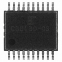
CS8130-CS Cirrus Logic Inc, CS8130-CS Datasheet - Page 8

CS8130-CS
Manufacturer Part Number
CS8130-CS
Description
IC IR TRANSCEIVER 2-5V 20-SSOP
Manufacturer
Cirrus Logic Inc
Type
Transceiverr
Datasheet
1.CS8130-CS.pdf
(28 pages)
Specifications of CS8130-CS
Mounting Type
Surface Mount
Voltage - Supply
2.7 V ~ 5.5 V
Package / Case
20-SSOP
Logic Case Style
SSOP
No. Of Pins
20
Peak Reflow Compatible (260 C)
No
Supply Voltage Max
5.5V
Transceiver Type
Infrared
Driver Case Style
SSOP
Leaded Process Compatible
No
Lead Free Status / RoHS Status
Contains lead / RoHS non-compliant
For Use With
598-1161 - BOARD EVAL FOR CS8130
Number Of Drivers/receivers
-
Protocol
-
Lead Free Status / RoHS Status
Contains lead / RoHS non-compliant, Contains lead / RoHS non-compliant
Other names
598-1203-5
Available stocks
Company
Part Number
Manufacturer
Quantity
Price
Part Number:
CS8130-CSZ
Manufacturer:
CIRRUS
Quantity:
20 000
then the RXD pin will oscillate at the carrier fre-
quency.
Transmit Path
Data for transmission is input to the CS8130 on
the TXD pin. The selected modulation scheme is
then applied to the data, and the resulting signals
are used to drive the LED. There are 2 LED out-
put pins: LED1C and LED2C. They are open
drain outputs, which pull down to TGND or
float. The LED is connected via resistors to both
LED1C and LED2C. The current level flowing
through the LED is determined by the external
resistors. Normally, LED1C is used to drive the
LED. If additional current is needed, (for exam-
ple for TV remote operation), then the second
driver may be enabled. The amount of ’boost’
current is determined by the external resistor
connected to the LED2C pin.
For larger amounts of IR output, it may be pref-
erable to use two LEDs, rather than drive a large
current through one LED. For a +3V supply sys-
tem using two LEDs, each one is connected, via
a resistor, to each driver output. For a +5V sup-
ply system, 2 LEDS may be connected in series,
and then routed to each driver via 2 resistors,
one for each driver. This minimizes the power
dissipation in the resistors.
Mode 1 Transmit Choices
In Mode 1 (IrDA), the pulse width may be fixed
at 1.6 s, or set to 3/16 of the bit period. Either
of these settings will meet the IrDA standard, but
fixed 1.6 s pulses will save power at lower
baud rates.
In addition, there is a choice which affects the
output pulse jitter. The default state causes the
CS8130 to look for the start bit on TXD. All
subsequent LED transitions for that character are
timed relative to the internal baud rate clock.
Therefore there will be no jitter in the LED out-
8
8
put pulse timing. However, the CS8130 now has
to be programmed with the desired number of
bits per character, which for IrDA compliance, is
8.
Alternatively, the CS8130 can generate output
pulses based entirely on individual transitions on
TXD, with no knowledge of which bit is the
start bit. Thus a 1 to 0 transition will generate a
pulse based on that transition edge. If TXD is
low for multiple successive bits, then the
CS8130 will generate pulses based on its internal
clock. Therefore there is the possibility of jitter
in the output pulses of N*271 ns. N can be 0, 1
2....., depending on the difference in frequency
between the UART baud rate clock and the
CS8130 clock. Clearly, if the CS8130 and its as-
sociated UART are running from the same clock,
the possibility of jitter is eliminated.
Mode 2 (ASK) Transmit Choices
The modulation frequency is determined by the
modulator divider registers. For nominal
500 kHz, use a divide value of 6, which yields a
modulation frequency of 527 kHz.
Mode 3 (TV Remote) Transmit Choices
During transmission of IR, the start and stop bits
present in the incoming data from the UART are
stripped off (see Figure 5). The remaining data
bits are then sent out at ~2400 bps. Since there
should be no gaps in the transmitted data, the
input data is buffered in a 22-character location
FIFO. Characters can be received on the TXD
pin while the previous characters are being trans-
mitted. To prevent overflow, a hardware
handshake mechanism is provided. If the FIFO
is one character away from being full, the
FORM/BSY pin is brought high, indicating that
the UART should not send any more data. Once
ano ther character has been transmitted,
FORM/BSY pin is brought low, indicating to the
UART that it is OK to send another character.
CS8130
CS8130
DS134PP2
DS134F1


