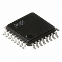
TDA8020HL/C1,118 NXP Semiconductors, TDA8020HL/C1,118 Datasheet - Page 14

TDA8020HL/C1,118
Manufacturer Part Number
TDA8020HL/C1,118
Description
IC SMART CARD INTERFACE 32LQFP
Manufacturer
NXP Semiconductors
Type
Interfacer
Datasheet
1.TDA8020HLC2118.pdf
(28 pages)
Specifications of TDA8020HL/C1,118
Voltage - Supply
2.7 V ~ 6.5 V
Mounting Type
Surface Mount
Package / Case
32-LQFP
Lead Free Status / RoHS Status
Lead free / RoHS Compliant
Number Of Drivers/receivers
-
Protocol
-
Other names
568-3523-2
935267381118
TDA8020HLBD-T
935267381118
TDA8020HLBD-T
Available stocks
Company
Part Number
Manufacturer
Quantity
Price
Company:
Part Number:
TDA8020HL/C1,118
Manufacturer:
NXP Semiconductors
Quantity:
10 000
Philips Semiconductors
V
Each card is supplied by a separate V
buffers are supplied by the same multimode capacitive
DC-to-DC converter.
In all modes (follower, doubler and tripler), the DC-to-DC
converter is able to deliver 80 mA over the whole V
range (2.7 to 6.5 V) or 120 mA if V
The current in each V
around 90 mA. When one of the buffers reaches this limit,
an automatic deactivation sequence is performed.
Each V
capacitor with a value of between 100 and 200 nF. If the
card socket is not very close to the device, one capacitor
should be connected close to the device, and a second
one connected close to card contact C1.
Protections
The current on pin CLK is limited to within the range
+70 mA and 70 mA.
The current on pin RST is limited to within the range
+20 mA and 20 mA; if the current reaches this value with
2003 Nov 06
handbook, full pagewidth
CC
Dual IC card interface
buffers
CC
supply voltage should be decoupled by an ESR
START/STOP
RST
CLK
I/O
V CC
V UP
CC
buffer is limited internally to
t10 t11
DD
> 3 V.
CC
buffer. Both
t12
Fig.5 Deactivation sequence.
t de
DD
t13
14
t14
RST LOW, then an emergency deactivation sequence is
performed, IRQ is pulled LOW and bit PROT is set in the
status register.
The current on pins I/O is limited to within the range
+15 mA and 15 mA.
The current on V
value, then an emergency deactivation sequence is
performed, IRQ is pulled LOW and bit PROT is set in the
status register.
In the event of overcurrent on V
session, overheating, or overcurrent on RST, then the
TDA8020HL performs an automatic emergency
deactivation sequence on the corresponding card, resets
bit START/STOP and pulls pin IRQ LOW.
In the event of overheating or supply drop-out, or
DC-to-DC converter out of specification, the TDA8020HL
performs an automatic emergency deactivation sequence
on both cards, resets both bits START/STOP and pulls
pin IRQ LOW.
t15
CC
is limited to 90 mA; if I
CC
, card take-off during a
FCE836
TDA8020HL
Product specification
CC
reaches this


