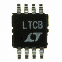
LTC1482CMS8 Linear Technology, LTC1482CMS8 Datasheet - Page 13

LTC1482CMS8
Manufacturer Part Number
LTC1482CMS8
Description
IC TXRX RS485 LOWPWR 8-MSOP
Manufacturer
Linear Technology
Type
Transceiverr
Datasheet
1.LTC1482CN8.pdf
(16 pages)
Specifications of LTC1482CMS8
Number Of Drivers/receivers
1/1
Protocol
RS422, RS485
Voltage - Supply
4.75 V ~ 5.25 V
Mounting Type
Surface Mount
Package / Case
8-MSOP, Micro8™, 8-uMAX, 8-uSOP,
Lead Free Status / RoHS Status
Contains lead / RoHS non-compliant
Available stocks
Company
Part Number
Manufacturer
Quantity
Price
Company:
Part Number:
LTC1482CMS8
Manufacturer:
LT
Quantity:
10 000
Part Number:
LTC1482CMS8
Manufacturer:
LINEAR/凌特
Quantity:
20 000
Company:
Part Number:
LTC1482CMS8#PBF
Manufacturer:
Linear Technology
Quantity:
135
Part Number:
LTC1482CMS8#PBF
Manufacturer:
LINEAR/凌特
Quantity:
20 000
Part Number:
LTC1482CMS8#TRPBF
Manufacturer:
LINEAR/凌特
Quantity:
20 000
APPLICATIONS
The supply current does not drop below 20 A immedi-
ately. DE and DI/SHDN must be low for a least 600ns
simultaneously for I
(driver outputs unloaded) and for t
ping to the 20 A level. Taking either DE or DI/SHDN high
will wake the LTC1482 within 5 s.
In some applications, the A and B lines are pulled to V
GND through external resistors to force the line to a high
or low state when all connected drivers are disabled. In
shutdown, the supply current will be higher than 10 A due
to the additional current drawn through the external pull-
up and the 22k input resistance of the LTC1482.
ESD Protection
The ESD performance of the LTC1482 A and B pins is
characterized to meet 15kV using the Human Body
Model (100pF, 1.5k ), IEC-1000-4-2 Level 4 ( 8kV)
contact mode and IEC-1000-4-2 Level 3 ( 8kV) air dis-
charge mode. This means that external voltage suppres-
sors are not required in many applications, when com-
pared with parts that are only protected to 2kV. Pins
other than the A and B pins are protected to 3kV typical
per the Human Body Model.
When powered up, the LTC1482 does not latch up or
sustain damage when the A and B pins are tested using any
of the three conditions listed. The data during the ESD
event may be corrupted, but after the event the LTC1482
continues to operate normally. The additional ESD protec-
tion at the A and B pins is important in applications where
these pins are exposed to the external world via connec-
tions to sockets.
U
CC
to drop to half its operating value
INFORMATION
U
CDH(SHDN)
W
before drop-
U
CC
or
Fault Protection
When shorted to – 7V or 10V at room temperature, the
short-circuit current in the driver pins is limited by internal
protection circuitry to 250mA. Over the industrial tem-
perature range, the absolute maximum positive voltage at
any driver pin should be limited to 10V to avoid damage to
the part. At higher ambient temperatures, the rise in die
temperature, due to the short-circuit current, may trip the
thermal shutdown circuit. This circuit protects the part
against prolonged shorts at the driver outputs. If a driver
output is shorted to another output or to V
will be limited to 250mA. If the die temperature rises above
150 C, the thermal shutdown circuit three-states the
driver outputs to open the current path. When the die cools
down to about 130 C, the driver outputs are taken out of
three-state. If the short persists, the part will heat again
and the cycle will repeat. This thermal oscillation occurs at
about 10Hz and protects the part from excessive power
dissipation. The average fault current drops as the driver
cycles between active and three-state. When the short is
removed, the part will return to normal operation.
When the driver is disabled, the receiver inputs can
withstand the entire – 7V to 12V RS485 common mode
range without damage.
LTC1482
CC
, the current
13


