A000003 Arduino, A000003 Datasheet - Page 273
A000003
Manufacturer Part Number
A000003
Description
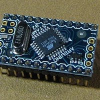
MCU, MPU & DSP Development Tools MINI
Manufacturer
Arduino
Series
-r
Type
MCUr
Specifications of A000003
Processor To Be Evaluated
Atmega328
Processor Series
ATmega
Data Bus Width
8 bit
Interface Type
USB, RS-232
Operating Supply Voltage
7 V to 9 V
Contents
Board
Lead Free Status / Rohs Status
Lead free / RoHS Compliant
For Use With/related Products
ATmega168


26.7
2545S–AVR–07/10
Addressing the Flash During Self-Programming
Table 26-4.
Note:
The Z-pointer is used to address the SPM commands.
Since the Flash is organized in pages (see
be treated as having two different sections. One section, consisting of the least significant bits, is
addressing the words within a page, while the most significant bits are addressing the pages.
This is1 shown in
addressed independently. Therefore it is of major importance that the Boot Loader software
addresses the same page in both the Page Erase and Page Write operation. Once a program-
ming operation is initiated, the address is latched and the Z-pointer can be used for other
operations.
The only SPM operation that does not use the Z-pointer is Setting the Boot Loader Lock bits.
The content of the Z-pointer is ignored and will have no effect on the operation. The LPM
instruction does also use the Z-pointer to store the address. Since this instruction addresses the
Flash byte-by-byte, also the LSB (bit Z0) of the Z-pointer is used.
Bit
ZH (R31)
ZL (R30)
BOOTRST
1
0
1. “1” means unprogrammed, “0” means programmed
Boot Reset Fuse
Z15
15
Z7
7
Reset Address
Reset Vector = Application Reset (address 0x0000)
Reset Vector = Boot Loader Reset (see
Figure
Z14
14
Z6
6
26-3. Note that the Page Erase and Page Write operations are
(1)
Z13
13
Z5
5
Table 27-9 on page
Z12
12
Z4
4
Z11
11
Z3
Table 26-6 on page
3
ATmega48/88/168
Z10
10
Z2
2
288), the Program Counter can
280)
Z9
Z1
9
1
Z8
Z0
8
0
273
Related parts for A000003
Image
Part Number
Description
Manufacturer
Datasheet
Request
R

Part Number:
Description:
Daughter Cards & OEM Boards ARDUINO UNO PROTO PCB REV 3
Manufacturer:
Arduino
Part Number:
Description:
Daughter Cards & OEM Boards ARDUINO SHIELD PROTO KIT REV 3
Manufacturer:
Arduino
Part Number:
Description:
Daughter Cards & OEM Boards ARDUINO MEGA PROTO KIT REV 3
Manufacturer:
Arduino
Part Number:
Description:
Daughter Cards & OEM Boards ARDUINO MEGA PROTO PCB REV 3
Manufacturer:
Arduino
Part Number:
Description:
Development Boards & Kits - AVR ARDUINO STARTER KIT W/ UNO REV3
Manufacturer:
Arduino
Part Number:
Description:
RF Development Tools ARDUINO SHIELD WIRELESS PROTO
Manufacturer:
Arduino
Datasheet:
Part Number:
Description:
RF Development Tools ARDUINO SHIELD WIRELESS WITH SD
Manufacturer:
Arduino
Datasheet:

Part Number:
Description:
Development Software Getting started w/Arduino
Manufacturer:
Arduino

Part Number:
Description:
Ethernet Modules & Development Tools Ethernet Shield for Arduino
Manufacturer:
Arduino

Part Number:
Description:
MCU, MPU & DSP Development Tools LilyPad Arduino Main Board
Manufacturer:
Arduino

Part Number:
Description:
ARDUINO NANO Board
Manufacturer:
Arduino
Datasheet:
Part Number:
Description:
Ethernet Modules & Development Tools ETHERNET SHEILD PoE FOR ARDUINO
Manufacturer:
Arduino
Datasheet:

Part Number:
Description:
ATMEGA328 MCU IC W/ Arduino UNO Bootloader
Manufacturer:
Arduino
Datasheet:
Part Number:
Description:
Memory Cards MICRO SD CARD 1GB WITH SD ADAPTER
Manufacturer:
Arduino