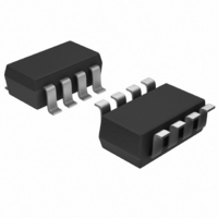
MAX9171EKA+T Maxim Integrated Products, MAX9171EKA+T Datasheet

MAX9171EKA+T
Specifications of MAX9171EKA+T
Related parts for MAX9171EKA+T
MAX9171EKA+T Summary of contents
Page 1
... GND N. N.C. SO/TDFN* ________________________________________________________________ Maxim Integrated Products For pricing, delivery, and ordering information, please contact Maxim Direct at 1-888-629-4642, or visit Maxim’s website at www.maxim-ic.com. o Input Accepts LVDS and LVPECL o In-Path Fail-Safe Circuit o Space-Saving 8-Pin TDFN and SOT23 Packages o Fail-Safe Circuitry Sets Output High for Open, ...
Page 2
Single/Dual LVDS Line Receivers with “In-Path” Fail-Safe ABSOLUTE MAXIMUM RATINGS V to GND ...........................................................-0.3V to +4.0V CC IN_+, IN_- to GND .................................................-0.3V to +4.0V OUT_ to GND ............................................-0. Continuous Power Dissipation (T = +70°C) A 8-Pin SOT23 (derate ...
Page 3
Single/Dual LVDS Line Receivers with SWITCHING CHARACTERISTICS (V = 3.0V to 3.6V 15pF 0.2V 3.3V +25°C.) (Notes PARAMETER SYMBOL Differential Propagation Delay High to Low ...
Page 4
Single/Dual LVDS Line Receivers with “In-Path” Fail-Safe (V = 3.3V 1.2V 0.2V OUTPUT HIGH VOLTAGE vs. SUPPLY VOLTAGE 3 -4mA OH 3.5 3.4 3.3 3.2 3.1 3.0 2.9 ...
Page 5
Single/Dual LVDS Line Receivers with (V = 3.3V 1.2V 0.2V DIFFERENTIAL PULSE SKEW vs. SUPPLY VOLTAGE 120 3.0 3.1 3.2 3.3 3.4 3.5 SUPPLY VOLTAGE (V) DIFFERENTIAL ...
Page 6
Single/Dual LVDS Line Receivers with “In-Path” Fail-Safe PIN NAME SOT23 SO/TDFN GND 3 7 OUT N. IN IN- — onl y) ...
Page 7
Single/Dual LVDS Line Receivers with V CC 2.5µA IN_+ 40mV IN_- 5µA Figure 1. Input with In-Path Fail-Safe Network Equivalent Circuit IN_+ PULSE IN_- GENERATOR 50Ω 50Ω Figure 2. Propagation Delay and Transition Test Time Circuit IN_- 1.2V (0V DIFFERENTIAL) ...
Page 8
Single/Dual LVDS Line Receivers with “In-Path” Fail-Safe ESD protection structures are incorporated on all pins to protect against electrostatic discharges encountered during handling and assembly. The receiver inputs of the MAX9171/MAX9172 have extra protection against static electricity. These pins are ...
Page 9
Single/Dual LVDS Line Receivers with (The package drawing(s) in this data sheet may not reflect the most current specifications. For the latest package outline information www.maxim-ic.com/packages.) _______________________________________________________________________________________ “In-Path” Fail-Safe Package Information 9 ...
Page 10
Single/Dual LVDS Line Receivers with “In-Path” Fail-Safe (The package drawing(s) in this data sheet may not reflect the most current specifications. For the latest package outline information www.maxim-ic.com/packages TOP VIEW FRONT VIEW ...
Page 11
Single/Dual LVDS Line Receivers with (The package drawing(s) in this data sheet may not reflect the most current specifications. For the latest package outline information www.maxim-ic.com/packages.) ______________________________________________________________________________________ “In-Path” Fail-Safe Package Information (continued) 11 ...
Page 12
... Maxim cannot assume responsibility for use of any circuitry other than circuitry entirely embodied in a Maxim product. No circuit patent licenses are implied. Maxim reserves the right to change the circuitry and specifications without notice at any time. 12 ____________________Maxim Integrated Products, 120 San Gabriel Drive, Sunnyvale, CA 94086 408-737-7600 © 2007 Maxim Integrated Products Package Information (continued) PACKAGE VARIATIONS PKG ...


