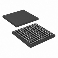
DS3154+ Maxim Integrated Products, DS3154+ Datasheet - Page 11

DS3154+
Manufacturer Part Number
DS3154+
Description
IC LIU DS3/E3/STS1 QUAD 144CSBGA
Manufacturer
Maxim Integrated Products
Type
Line Interface Units (LIUs)r
Datasheet
1.DS3151.pdf
(61 pages)
Specifications of DS3154+
Number Of Drivers/receivers
4/4
Protocol
IEEE 1149.1
Voltage - Supply
3.135 V ~ 3.465 V
Mounting Type
Surface Mount
Package / Case
144-CSBGA
Lead Free Status / RoHS Status
Lead free / RoHS Compliant
Table 4-B. Transmitter Pin Descriptions
TPOSn/
TDSAn,
TNEGn
TDSBn
TCLKn
TDATn
TLBOn
NAME
TXPn,
TDMn
TXNn
TJAn
TTSn
I/O
O3
O
I
I
I
I
I
I
I
Transmitter Clock. A DS3 (44.736MHz ±20ppm), E3 (34.368MHz ±20ppm), or STS-1 (51.840MHz
±20ppm) clock should be applied at this signal. Data to be transmitted is clocked into the device at
TPOS/TDAT and TNEG either on the rising edge of TCLK (TCINV = 0) or the falling edge of TCLK
(TCINV = 1). See Section
Transmitter Positive AMI/Transmitter Data. When the transmitter is configured to have a bipolar
interface (TBIN = 0), a positive pulse is transmitted on the line when TPOS is high. When the
transmitter is configured to have a binary interface (TBIN = 1), the data on TDAT is transmitted after
B3ZS or HDB3 encoding. TPOS/TDAT is sampled either on the rising edge of TCLK (TCINV = 0) or
on the falling edge of TCLK (TCINV = 1).
Transmitter Negative AMI. When the transmitter is configured to have a bipolar interface (TBIN = 0), a
negative pulse is transmitted on the line when TNEG is high. When the transmitter is configured to
have a binary interface (TBIN = 1), TNEG is ignored and should be wired either high or low. TNEG is
sampled either on the rising edge of TCLK (TCINV = 0) or on the falling edge of TCLK (TCINV = 1).
Transmitter Analog Outputs. These differential AMI outputs are coupled to the outbound 75Ω coaxial
cable through a 2:1 step-down transformer
pin or the TTS or TPS configuration bits.
Transmitter Tri-State Enable (Active Low). TTS tri-states the transmitter outputs (TXP and TXN). This
feature supports applications requiring LIU redundancy. Transmitter outputs from multiple LIUs can be
wire-ORed together, eliminating external switches. The transmitter continues to operate internally
when TTS is active.
0 = tri-state the transmitter output driver
1 = enable the transmitter output driver
Transmitter Driver Monitor (Active Low, Open Drain). TDM reports the status of the transmit driver
monitor. When the transmit driver monitor detects a faulty transmitter, TDM is driven low. TDM
requires an external pullup to V
Transmitter Data Select. These inputs select the source of the transmit data. See
Transmitter Line Build-Out Enable. TLBO indicates cable length for waveform shaping in DS3 and
STS-1 modes. TLBO is ignored for E3 mode and should be wired high or low.
0 = cable length ≥ 225ft
1 = cable length < 225ft
Transmitter Jitter Attenuator Enable
0 = remove jitter attenuator from the transmitter path
1 = insert jitter attenuator into the transmitter path
(Note that TJA = 1 takes precedence over RJA = 1.)
DS3151/DS3152/DS3153/DS3154 Single/Dual/Triple/Quad DS3/E3/STS-1 LIUs
7
for additional details.
DD
.
11 of 61
(Figure
FUNCTION
1-1). These outputs can be tri-stated using the TTS
Table 4-F
for details.


