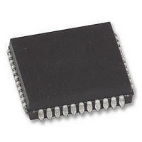
VRS51C1000-40-LG-ISPV2 Ramtron, VRS51C1000-40-LG-ISPV2 Datasheet - Page 27

VRS51C1000-40-LG-ISPV2
Manufacturer Part Number
VRS51C1000-40-LG-ISPV2
Description
Microcontrollers (MCU) 64K+1K 40MHz 5V
Manufacturer
Ramtron
Datasheet
1.VRS51C1000-40-PG.pdf
(48 pages)
Specifications of VRS51C1000-40-LG-ISPV2
Data Bus Width
8 bit
Program Memory Type
Flash
Program Memory Size
64 KB
Data Ram Size
1 KB
Interface Type
UART
Maximum Clock Frequency
40 MHz
Number Of Programmable I/os
36
Number Of Timers
3
Operating Supply Voltage
4.5 V to 5.5 V
Maximum Operating Temperature
+ 85 C
Mounting Style
SMD/SMT
Package / Case
PLCC-44
Minimum Operating Temperature
- 40 C
Lead Free Status / Rohs Status
Details
The value to write into the TH1 register is defined by
the following formula:
Generating UART Baud Rates with Timer 2
Timer 2 is often preferred to generate the baud rate, as
it can be easily configured to operate as a 16-bit timer
with auto-reload. This allows for much better resolution
than using Timer 1 in 8-bit auto-reload mode.
The baud rate using Timer 2 is defined as:
The timer can be configured as either a timer or a
counter in any of its 3 running modes. In most typical
applications, it is configured as a timer (C/T2 is set to
0).
To make the Timer 2 operate as a baud rate generator,
the TCLK and RCLK bits of the T2CON register must
be set to 1.
The baud rate generator mode is similar to the auto-
reload mode in that an overflow in TH2 causes the
Timer 2 registers to be reloaded with the 16-bit value in
registers RCAP2H and RCAP2L, which are preset by
software. However, when Timer 2 is configured as a
baud rate generator, its clock source is Osc/2.
______________________________________________________________________________________________
www.ramtron.com
VRS51C1000
TH1 = 256 -
Mode 1,3 Baud Rate = Timer 2 Overflow Rate
32 x 12x (Baud Rate)
2
SMOD
x Fosc
16
The following formula can be used to calculate the
baud rate in modes 1 and 3 using the Timer 2:
(NTD where are the formulas?)
The formula below is used to define the reload value to
put into the RCAP2h, RCAP2L registers to achieve a
given baud rate.
In the above formula, RCAP2H and RCAP2L are the
content of RCAP2H and RCAP2L taken as a 16-bit
unsigned integer.
Note that a rollover in TH2 does not set TF2, and will
not generate an interrupt and because of this, Timer 2
interrupt does not have to be disabled when Timer 2 is
configured in baud rate generator mode.
Furthermore, when Timer 2 is configured as UART
baud rate generator and running (TR2 is set to 1), the
user should not try to perform read or write operations
to the TH2 or TL2 and RCAP2H, RCAP2L registers
(RCAP2H, RCAP2L) = 65536 -
Modes 1, 3 Baud Rate =
32x[65536 – (RCAP2H, RCAP2L)]
Oscillator Frequency
32x[Baud Rate]
page 27 of 48
Fosc


