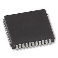
VRS51C1000-40-LG-ISPV2 Ramtron, VRS51C1000-40-LG-ISPV2 Datasheet - Page 31

VRS51C1000-40-LG-ISPV2
Manufacturer Part Number
VRS51C1000-40-LG-ISPV2
Description
Microcontrollers (MCU) 64K+1K 40MHz 5V
Manufacturer
Ramtron
Datasheet
1.VRS51C1000-40-PG.pdf
(48 pages)
Specifications of VRS51C1000-40-LG-ISPV2
Data Bus Width
8 bit
Program Memory Type
Flash
Program Memory Size
64 KB
Data Ram Size
1 KB
Interface Type
UART
Maximum Clock Frequency
40 MHz
Number Of Programmable I/os
36
Number Of Timers
3
Operating Supply Voltage
4.5 V to 5.5 V
Maximum Operating Temperature
+ 85 C
Mounting Style
SMD/SMT
Package / Case
PLCC-44
Minimum Operating Temperature
- 40 C
Lead Free Status / Rohs Status
Details
Modifying the Order of Priority
The VRS51C1000 allows the user to modify the natural
priority of the interrupts. One may modify the order by
programming the bits in the IP (Interrupt Priority)
register. When any bit in this register is set to 1, it
gives the corresponding source a greater priority than
interrupts coming from sources that don’t have their
corresponding IP bit set to 1.
The IP register is represented in the table below.
T
Watchdog Timer
The Watchdog Timer (WDT) is a 16-bit free-running
counter that generates a reset signal if the counter
overflows. The WDT is useful for systems that are
susceptible to noise, power glitches and other
conditions that can cause the software to go into
infinite dead loops or runaways. The WDT function
gives the user software a recovery mechanism from
abnormal software conditions. The WDT is different
from Timer 0, Timer 1 and Timer 2 of the standard
8051.
Once the WDT is enabled, the user software must
clear it periodically. In the case where the WDT is not
cleared, its overflow will trigger a reset of the
VRS51C1000.
The user should check the WDR bit of the SYSCON
register whenever an unpredicted reset has taken
place.
The WDT timeout delay can be adjusted by configuring
the clock divider input for the time base source clock of
the WDT. To select the divider value, bit2-bit0 (PS2-
PS0) of the Watchdog Timer Control Register (WDTC)
should be set accordingly.
To enable the WDT, the user must set bit 7 (WDTE) of
the WDTC register to 1. Once WDTE has been set to
1, the 16-bit counter will start to count with the selected
time base source clock configured in PS2~PS0. The
______________________________________________________________________________________________
www.ramtron.com
ABLE
5
4
3
2
1
0
Bit
7
6
VRS51C1000
EA
7
35: IP I
PT2
PS
PT1
PX1
PT0
PX0
Mnemonic
-
-
NTERRUPT
6
-
P
ET2
RIORITY
5
Description
Gives Timer 2 Interrupt Higher Priority
Gives Serial Port Interrupt Higher Priority
Gives Timer 1 Interrupt Higher Priority
Gives INT1 Interrupt Higher Priority
Gives Timer 0 Interrupt Higher Priority
Gives INT0 Interrupt Higher Priority
R
EGISTER
ES
4
–SFR B8
ET1
3
H
EX1
2
ET0
1
EX0
0
Watchdog Timer will generate a reset signal if an
overflow has taken place. The WDTE bit will be
cleared to 0 automatically when VRS51C1000 has
been reset by either the hardware or a WDT reset.
Clearing the WDT is accomplished by setting the CLR
bit of the WDTC to 1. This action will clear the contents
of the 16-bit counter and force it to restart.
Watchdog Timer Registers
Two of the registers of the VRS51C1000 are
associated with the Watchdog Timer: WDTC and
SYSCON.
enable the WDT, clear the counter and to divide the
clock source. The WDR bit of the SYSCON register
indicates whether the Watchdog Timer caused the
device reset.
T
The
associated with different values of the PSx bits of the
Watchdog Timer Register.
T
ABLE
ABLE
Bit
7
6
5
[4:3]
2
1
0
PS [2:0]
WDTE
000
001
010
011
100
101
110
111
7
36: W
37: T
following
IME
ATCHDOG
P
Unused
Mnemonic
WDTE
Unused
CLR
Unused
PS2
PS1
PS0
ERIOD AT
(OSC in)
The WDTC register allows the user to
Divider
6
1024
T
128
256
512
IMER
16
32
64
8
40MH
R
table
EGISTERS
CLR
Z
5
, 22.184MH
Description
Watchdog Timer Enable Bit
-
Watchdog Timer Counter Clear Bit
-
Clock Source Divider Bit 2
Clock Source Divider Bit 1
Clock Source Divider Bit 0
1677.72
104.86
209.72
419.43
838.86
40MHz
Period
: WDTC – SFR 9F
13.11
26.21
52.43
WDT
provides
Unused
4
Z AND
3
11.059MH
page 31 of 48
22.18MHz
1512.55
3025.10
189.07
378.14
756.28
Period
23.63
47.27
94.53
PS2
WDT
H
timeout
2
Z
PS1
1
1398.10
2796.20
5592.41
174.76
349.53
699.05
12MHz
Period
43.69
87.38
WDT
periods
PS0
0


