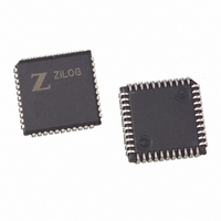
Z0220112VSGR4078 Zilog, Z0220112VSGR4078 Datasheet - Page 68

Z0220112VSGR4078
Manufacturer Part Number
Z0220112VSGR4078
Description
IC MODEM 2400BPS DSP AFE 44-PLCC
Manufacturer
Zilog
Specifications of Z0220112VSGR4078
Data Format
V.21, V.22, V.23, Bell 103, Bell 212A
Baud Rates
2.4k
Interface
Parallel
Voltage - Supply
4.5 V ~ 5.5 V
Mounting Type
Surface Mount
Package / Case
44-LCC (J-Lead)
Lead Free Status / RoHS Status
Lead free / RoHS Compliant
Available stocks
Company
Part Number
Manufacturer
Quantity
Price
PS000904-0107
Enabling HDLC Operation
Transmitting
A flag, byte value
abort, which is any sequence of consecutive binary 1s more than six bits long. If
the frames do not use the bandwidth of the data mode (for example, when there is
no host data to transmit), the modem fills the remaining bandwidth by sending
flags between frames.
Frame data bytes for transmission are supplied by the host to the data pump’s
DATAP register. These bytes are modified by the data pump to ensure that no
more than five consecutive binary
the transmitting modem inserts a single
bits in the host supplied data. This zero insertion process allows the receiving
modem’s data pump to distinguish between frame data, flags, and aborts. The
receiving modem’s data pump uses a zero deletion process to remove each
inserted
When a frame is to be closed, the frame's two CRC checksum bytes are sent
immediately following the frame data. The CRC checksum is computed without
the inserted zeroes. The frame’s closing flag is transmitted following the CRC.
This flag may also serve as the opening flag of the next frame, saving bandwidth.
The data pump’s HDLC firmware is disabled at power-up and any reset, and can
be enabled only in parallel mode (Reg4., bit
BUFCTRL, bit
mode operation. The host also reads register DATAP just before starting data
mode to clear DATAP.
These examples demonstrate the use of the data pump in parallel mode to trans-
mit and receive HDLC data frames. The examples assume that the data pump
has just been put in data mode, and HDLC operation is enabled. The data to be
sent or received is the sequence of N bytes (Byte1–ByteN), where Byte1 is sent
(or received) first.
1. When Reg5, bit
2. When the last byte, ByteN, has been sent, wait for the data pump to set Reg7,
byte to be transmitted. If Reg4, bit
interrupt when it is ready to transmit the next byte, for example, when the byte
sets Reg5, bit
bit
frame. The data pump now computes and transmits the CRC checksum and
closing flag for the frame. The data pump does not set Reg7, bit
2
(TEND) to
0
bit before returning the data to the receiving modem's host.
7
(HDLC) to
07Eh
7
1
7
. This function indicates the data pump has closed the current
(TXI) to
(TXI) is
, is one of two HDLC control symbols. The other is an
1
, and bits 8–15 of BUFCTRL to 0 prior to beginning data
1
.
1
, write Byte1 to DATAP. Repeat this step for each
1
bits are sent. To accomplish this modification,
7
V.22BIS Data Pump with Integrated AFE
0
(TXIE) is
bit after every five consecutive binary 1
4
(TPDM) is 1). To enable HDLC, set
1
, the data pump generates an
7
(TEND) to
1
64


