AD693AQ Analog Devices Inc, AD693AQ Datasheet - Page 8
AD693AQ
Manufacturer Part Number
AD693AQ
Description
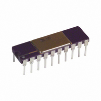
IC TRANSMITTER 4-20MA 20-CDIP
Manufacturer
Analog Devices Inc
Type
Signal Conditionerr
Datasheet
1.AD693AQ.pdf
(12 pages)
Specifications of AD693AQ
Rohs Status
RoHS non-compliant
Input Type
Voltage
Output Type
Voltage
Interface
3-Wire
Current - Supply
20mA
Mounting Type
Through Hole
Package / Case
20-CDIP (0.300", 7.62mm)
Supply Voltage Range
12V To 36V
Operating Temperature Range
-40°C To +85°C
Digital Ic Case Style
DIP
No. Of Pins
20
Svhc
No SVHC (18-Jun-2010)
Operating Temperature Max
85°C
Operating
RoHS Compliant
Converter Type
Voltage to Current
Current, Output
+25 mA (Typ.)
Current, Quiescent Supply
+500 uA (Typ.)
Package Type
Cerdip
Temperature, Operating, Maximum
85 °C
Temperature, Operating, Minimum
-40 °C
Voltage, Operating
+12 V (Min.)
No. Of Amplifiers
5
Input Offset Voltage
200µV
Cmrr
90dB
Supply Current
500µA
Amplifier Case Style
DIP
Rohs Compliant
No
Ic Function
Sensor Transmitter
Amplifier Type
Current
Base Number
693
Lead Free Status / RoHS Status
Available stocks
Company
Part Number
Manufacturer
Quantity
Price
Company:

Part Number:
AD693AQ
Manufacturer:
TOSHIBA
Quantity:
101
Part Number:
AD693AQ
Manufacturer:
ADI/亚德诺
Quantity:
20 000


AD693
An alternative arrangement, allowing wide range span adjust-
ment between two set ranges, is shown in Figure 13. R
R
previous formulae. The smallest value is then placed in series
with the wiper of the 1.5 k potentiometer shown in the figure.
For example, to adjust the span between 25 mV and 40 mV, R
and R
The smaller value, 800 , is then reduced by 10% to cover the
possible ranges of resistance in the AD693 and that value is put
in place.
A number of other arrangements can be used to set the span as
long as they are compatible with the pretrimmed noninverting
gain of two. The span adjustment can even include thermistors
or other sensitive elements to compensate the span of a sensor.
In devising your own adjustment scheme, remember that you
should adjust the gain such that the desired span voltage at the
Signal Amplifier input translates to 60 mV at the output. Note
also that the full differential voltage applied to the V/I converter
is 75 mV; in the 4-20 mA mode, –15 mV is applied to the
inverting input (zero pin) by the Divider Network and +60 mV
is applied to the noninverting input by the Signal Amplifier. In
the 0–20 mA mode, the total 75 mV must be applied by the
Signal Amplifier. As a result, the total span voltage will be 25%
larger than that calculated for a 4-20 mA output.
Finally, the external resistance from P2 to 6.2 V should not be
made less than 1 k unless the voltage reference is loaded to at
least 1.0 mA. (A simple load resistor can be used to meet this
requirement if a low value potentiometer is desired.) In no case
should the resistance from P2 to 6.2 V be less than 200 .
Input Spans Between 60 mV and 100 mV
Input spans of up to 100 mV can be obtained by adding an
offset proportional to the output signal into the zero pin of the
V/I converter. This can be accomplished with two resistors and
adjusted via the optional trim scheme shown in Figure 14. The
resistor divider formed by R
Signal Amplifier modifies the differential input voltage range
applied to the V/I converter.
In order to determine the fixed resistor values, R
measure the source resistance (R
This can be accomplished (power supply disconnected) by
measuring the resistance between the 4 mA of offset (Pin 13)
and common (Pin 6) with the 6.2 V reference (Pin 14) connected
to common. The measured value, R
R
S2
E1
are calculated to be 90% of the values determined from the
and R
S2
are calculated to be 2000
Figure 13. Wide Range Span Adjustment
E2
via the following formula:
E1
and R
D
) of the internal divider network.
D
and 800 , respectively.
E2
, is then used to calculate
from the output of the
E1
and R
S1
and
E2
, first
S1
–8–
Figure 14 shows a scheme for adjusting the modified span and
4 mA offset via R
connect both signal inputs to the 6.2 V Reference, set R
zero and then adjust R
This in effect, creates a divider with the same ratio as the
internal divider that sets the 4 mA zero level (–15 mV with
respect to 6.2 V). As long as the input signal remains zero the
voltage at Pin 12, the zero adjust, will remain at –15 mV with
respect to 6.2 V.
After adjusting R
signal inputs and adjust R
loop. An attenuated portion of the input signal is now added
into the V/I zero to maintain the 75 mV maximum differential.
If there is some small offset at the input to the Signal Amplifier,
it may be necessary to repeat the two adjustments.
LOCAL-POWERED OPERATION FOR 0–20 mA OUTPUT
The AD693 is designed for local-powered, three-wire systems as
well as two-wire loops. All its usual ranges are available in three-
wire operation, and in addition, the 0–20 mA range can be used.
The 0-20 mA convention offers slightly more resolution and
may simplify the loop receiver, two reasons why it is sometimes
preferred.
The arrangement, illustrated in Figure 15, results in a 0–20 mA
transmitter where the precalibrated span is 37.5 mV. Con-
necting P1 to P2 will double the span to 75 mV. Sensor input
and excitation is unchanged from the two-wire mode except for
the 25% increase in span. Many sensors are ratiometric so that
an increase in excitation can be used instead of a span
adjustment.
In the local-powered mode, increases in excitation are made
easier. Voltage compliance at the I
the loop voltage may be permitted to fall to 6 volts at the
AD693, easing the trade-off between loop voltage and loop
resistance. Note that the load resistor, R
current into Pin 10, I
with the local power supply current.
Figure 14. Adjusting for Spans between 60 mV and
100 mV (R
and R
R
E 2
E1
R
E1
= 412 R
D
and R
S 60 mV
E3
E3
place the desired full scale (S) across the
and R
E2
E2
IN
S
E3
) with Fine-Scale Adjust (R
, so as not to confuse the loop current
so that 4 mA flows in the current loop.
E4
E4
. The trim procedure is to first
so that 20 mA flows in the current
1.0024
IN
terminal is also improved;
L
, should meter the
E3
and R
E4
REV. A
to
E4
)
Related parts for AD693AQ
Image
Part Number
Description
Manufacturer
Datasheet
Request
R

Part Number:
Description:
±1.7g Dual-Axis IMEMS Accelerometer Evaluation Board
Manufacturer:
Analog Devices Inc
Datasheet:

Part Number:
Description:
Inertial Sensor Evaluation System
Manufacturer:
Analog Devices Inc
Datasheet:
Part Number:
Description:
Manufacturer:
Analog Devices Inc
Datasheet:
Part Number:
Description:
Manufacturer:
Analog Devices Inc
Datasheet:
Part Number:
Description:
Manufacturer:
Analog Devices Inc
Datasheet:
Part Number:
Description:
Manufacturer:
Analog Devices Inc
Datasheet:
Part Number:
Description:
Manufacturer:
Analog Devices Inc
Datasheet:
Part Number:
Description:
Manufacturer:
Analog Devices Inc
Datasheet:
Part Number:
Description:
Manufacturer:
Analog Devices Inc
Datasheet:
Part Number:
Description:
Manufacturer:
Analog Devices Inc
Datasheet:
Part Number:
Description:
Manufacturer:
Analog Devices Inc
Datasheet:
Part Number:
Description:
Manufacturer:
Analog Devices Inc
Datasheet:
Part Number:
Description:
Manufacturer:
Analog Devices Inc
Datasheet: