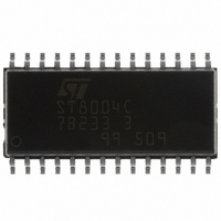
ST8004CDR STMicroelectronics, ST8004CDR Datasheet

ST8004CDR
Specifications of ST8004CDR
Available stocks
Related parts for ST8004CDR
ST8004CDR Summary of contents
Page 1
... Under voltage lockout protection selectable 2.2V ■ Supply supervisor integrated Order code Part number Temperature range ST8004CDR °C January 2007 generation Description The ST8004 is a complete low cost analog interface for asynchronous 3V and 5V smart cards. It can be placed between the card and the ...
Page 2
Contents Contents 1 Diagram . . . . . . . . . . . . . . . . . . . . . . . . . . . . . . . . . . . . ...
Page 3
ST8004 1 Diagram Figure 1. Block diagram Diagram 3/26 ...
Page 4
Pin configuration 2 Pin configuration Figure 2. Pin connections Table 1. Pin description Pin N° Symbol 1 CLKDIV1 Control of CLK Frequency 2 CLKDIV2 Control of CLK Frequency 3 5V/ PGND Power Ground for Step-Up converter 5 ...
Page 5
ST8004 Table 1. Pin description Pin N° Symbol 20 RSTIN Card Reset Input from MCU 21 V Supply Voltage DD 22 GND Ground 23 OFF Interrupt to MCU (active Low) 24 XTAL1 Crystal or external clock input 25 XTAL2 Crystal ...
Page 6
Maximum ratings 3 Maximum ratings Table 2. Absolute maximum ratings Symbol V V Supply voltage DD, DDP Voltage on pins XTAL1, XTAL2, 5V/3V, RSTIN, AUX2UC, V AUX1UC, I/OUC, CLKDIV1, CLKDIV2 PRES, PRES and OFF V Voltage on card ...
Page 7
ST8004 4 Electrical characteristics Table 5. Electrical characteristics over recommended operating (V 10MHz, unless otherwise noted. Typical values are to T Symbol Parameter V Supply voltage DD Supply voltage for the V DDP voltage doubler Output voltage on pin V ...
Page 8
Electrical characteristics Table 6. Card supply voltage characteristics (V unless otherwise noted. Typical values are to T Symbol Parameter Output voltage including V CC ripple V Peak to peak ripple I(RIPPLE) voltage on V (P- Output current ...
Page 9
ST8004 Table 9. Data lines (pins I/O, AUX1 AND AUX2 WITH 10 k Internally (V = 3.3V are 25°C) A Symbol Parameter High level output voltage data lines Low level output voltage ...
Page 10
Electrical characteristics Table 10. Data lines (pins I/OUC, AUX1UC AND AUX2UC with internally (V DD values are 25°C) A Symbol Parameter t Input transition times T(DI) t Output transition times T(DO) C Input ...
Page 11
ST8004 Table 14. Logic inputs (pins CLKDIV1, CLKDIV2, PRES, PRES, CMDV VTHSEL (V = 3.3V are 25°C) (Note 3) a Symbol Parameter V Low Level Input Voltage IL V High Level Input Voltage IH Input ...
Page 12
Waveforms 5 Waveforms Figure 3. Alarm as a function of V Figure 4. Alarm as a function of V 12/ ms THSEL ms GND DD W ...
Page 13
ST8004 Figure 5. Activation sequence Figure 6. Deactivation sequence Waveforms 13/26 ...
Page 14
Waveforms Figure 7. Behavior of OFF, CMDV Figure 8. Emergency deactivation sequence Figure 9. Definition of output transition times 14/26 , PRES and ST8004 ...
Page 15
ST8004 6 Functional description Throughout this document it is assumed that the reader is familiar with iso7816 norm terminology 6.1 Power supply The supply pins for the IC are V interface signals with the microcontroller are referenced to V voltage ...
Page 16
Functional description 6.4 Clock circuitry The clock signal (CLK) to the card is either derived from a clock signal input on the pin XTAL1 or from a crystal MHz connected between pins XTAL1 and XTAL2. The frequency ...
Page 17
ST8004 6.6 Inactive state After power-on reset, the circuit enters the inactive state. A minimum number of circuits are active while waiting for the microcontroller to start a session. ● All card contacts are inactive (approximately 200Ω to GND); I/OUC, ...
Page 18
Functional description It is recommended to: 1. Keep track C3 as far as possible from other tracks 2. Have straight connection between CGND and C5 (the 2 capacitors on C1 should be connected to this ground track) 3. Avoid ground ...
Page 19
ST8004 When OFF level falls low, the system controller must wait not less than 160µs before setting high again the CMDV Depending on the type of card presence switch within the connector (normally closed or normal open), and on the ...
Page 20
Functional description Figure 10. ST8004 Sequencer 20/26 ST8004 ...
Page 21
ST8004 Figure 11. Card control sequencer OFF_temp = PRES or (not PRES_NEG) CARD CONTROL CHANGE_OFF OFF = PRES or (not PRES_NEG) CMDVCC=0 OFF_temp = 1 LOCK_OFF_HIGH OFF=1 Removing Card after the Activation Sequence CMDVCC=0 OFF_temp = 0 Functional description CMDVCC=0 ...
Page 22
Package mechanical data 7 Package mechanical data In order to meet environmental requirements, ST offers these devices in ECOPACK® packages. These packages have a Lead-free second level interconnect. The category of second level interconnect is marked on the package and ...
Page 23
ST8004 DIM. MIN 0.1 b 0. 17.70 E 10. 7.40 L 0.50 S SO-28 MECHANICAL DATA mm. TYP MAX. 2.65 0.3 0.49 0.32 0.5 45˚ (typ.) 18.10 10.65 1.27 16.51 ...
Page 24
Package mechanical data DIM. MIN 12 10.8 Bo 18.2 Ko 2.9 Po 3.9 P 11.9 24/26 Tape & Reel SO-28 MECHANICAL DATA mm. TYP MAX. 330 13.2 30.4 11.0 18.4 3.1 4.1 ...
Page 25
ST8004 8 Revision history Table 19. Revision history Date Revision 18-Mar-2004 5 04-May-2006 6 31-Jan-2007 7 Pag. 10, fig. 4, RSTIN ==> CLK. Order code has been updated and new template. Change values V Min. and Max. on th3 Revision ...
Page 26
... Information in this document is provided solely in connection with ST products. STMicroelectronics NV and its subsidiaries (“ST”) reserve the right to make changes, corrections, modifications or improvements, to this document, and the products and services described herein at any time, without notice. All ST products are sold pursuant to ST’s terms and conditions of sale. ...


