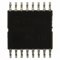
PM8800ATR STMicroelectronics, PM8800ATR Datasheet - Page 7

PM8800ATR
Manufacturer Part Number
PM8800ATR
Description
IC POE-PD PWM CTLR 16-HTSSOP
Manufacturer
STMicroelectronics
Datasheet
1.PM8800ATR.pdf
(35 pages)
Specifications of PM8800ATR
Applications
Power Over Ethernet (PoE)
Interface
IEEE 802.3af
Voltage - Supply
10 V
Package / Case
16-TSSOP Exposed Pad, 16-eTSSOP, 16-HTSSOP
Mounting Type
Surface Mount
For Use With
497-6366 - BOARD EVAL FOR PM8800A
Lead Free Status / RoHS Status
Lead free / RoHS Compliant
Other names
497-6897-2
PM8800ATR
PM8800ATR
Available stocks
Company
Part Number
Manufacturer
Quantity
Price
Company:
Part Number:
PM8800ATR
Manufacturer:
ON
Quantity:
300 000
Part Number:
PM8800ATR
Manufacturer:
ST
Quantity:
20 000
PM8800A
Table 2.
Pin#
10
11
12
13
14
15
16
7
8
9
COMP
AGND
Name
DCCL
nPGD
GND
VCC
VSS
VFB
GD
CS
EP
Pin description (continued)
DC current limit.
A resistor between DCCL and VSS will set the current limit for the interface
section of the PM8800A. It can be set to exceed the IEEE802.3af current limit.
Leave the pin open for standard IEEE 802.3af applications.
System low potential input.
System return for the PWM converter.
It is the drain of the internal hot-swap power MOSFET.
Output of the PWM controller. External power MOSFET gate driver output.
Output of the internal high voltage regulator.
When the auxiliary transformer winding (if used) raises the voltage on this pin
above the regulation set point, the internal regulator will be switched off, reducing
the controller power dissipation.
Power good, active low signal.
A high to low transition indicates that the inrush current phase has been
completed, the internal hot swap MOSFET is fully closed and the SMPS portion of
the PM8800A is activated.
Current sense input.
Current sense input for current mode control and over-current protection. Current
limiting is obtained with a dedicated current sense comparator. If the CS pin
voltage exceeds 0.5 V the GD pin switches low for cycle-by-cycle current limiting.
Leading edge blanking is implemented to mask current spikes.
The output of the error amplifier and input of the Pulse Width Modulator.
COMP pull-up is provided by an internal 2.5 kΩ resistor which may be used to
bias an opto-coupler transistor.
Feedback signal.
Inverting input of the internal error amplifier. The non-inverting input is internally
connected to a 1.25 V reference.
If not used must be grounded to AGND.
Analog PWM supply return.
GND for sensitive analog circuitry including the SMPS current limit circuitry. Must
be connected to GND to improve noise immunity.
Exposed pad.
Connect this to a board plane to improve heat dissipation; must be electrically
connected to VSS
Pins description and connection diagrams
Function
7/35


