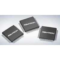
VRS51C1000-40-QG-ISPV2 Ramtron, VRS51C1000-40-QG-ISPV2 Datasheet - Page 32

VRS51C1000-40-QG-ISPV2
Manufacturer Part Number
VRS51C1000-40-QG-ISPV2
Description
Microcontrollers (MCU) 64K+1K 40MHz 5V
Manufacturer
Ramtron
Datasheet
1.VRS51C1000-40-PG.pdf
(48 pages)
Specifications of VRS51C1000-40-QG-ISPV2
Data Bus Width
8 bit
Program Memory Type
Flash
Program Memory Size
64 KB
Data Ram Size
1 KB
Interface Type
UART
Maximum Clock Frequency
40 MHz
Number Of Programmable I/os
36
Number Of Timers
3
Operating Supply Voltage
4.5 V to 5.5 V
Maximum Operating Temperature
+ 85 C
Mounting Style
SMD/SMT
Package / Case
QFP-44
Minimum Operating Temperature
- 40 C
Data Rom Size
128 B
Height
2 mm
Length
10 mm
Supply Voltage (max)
5.5 V
Supply Voltage (min)
4.5 V
Width
10 mm
Lead Free Status / Rohs Status
Details
T
BF
As previously mentioned, bit 7 (WDR) of SYSCON is
the Watchdog Timer Reset bit. It will be set to 1 when
a reset signal is generated by the WDT overflow. The
user should check the WDR bit whenever an
unpredicted reset has taken place.
Reduced EMI Function
The VRS51C1000 can also be set up for reduced EMI
(electromagnetic interference) by setting bit 0 (ALEI) of
the SYSCON register to 1. This function will inhibit the
Fosc/6Hz clock signal output to the ALE pin.
______________________________________________________________________________________________
www.ramtron.com
ABLE
Bit
7
[6:3]
2
1
0
WDR
VRS51C1000
H
7
38: W
Mnemonic
WDR
Unused
IAPE
XRAME
ALEI
ATCHDOG
6
T
IMER
5
Unused
R
EGISTER
Description
Watchdog Timer Reset Bit
-
ISP Overall Enable Bit
1: Enables ISP Function
0: Disables ISP Function
1: Enable Electromagnetic Interference
Reducer
0: Disable Electromagnetic Interference
Reducer
4
-S
YSTEM
C
3
ONTROL
IAPE
R
2
EGISTER
XRAME
(SYSCON)–SFR
1
ALEI
0
Pulse Width Modulation (PWM)
The Pulse Width Modulation (PWM) module consists
of five 8-bit channels. Each channel uses an 8-bit
PWM data register (PWMD) to set the number of
continuous pulses within a PWM frame cycle.
PWM Function Description:
Each 8-bit PWM channel is composed of an 8-bit
register that consists of a 5-bit PWM (5 MSBs) and a
3-bit (LSBs) Narrow Pulse Generator (NP). The 5-bit
PWM determines the duty cycle of the output. The 3-bit
NPx generates and inserts narrow pulses among the
PWM frame made of 8 cycles.
The number of pulses generated is equal to the
number programmed intp the 3-bit NP. The NP is used
to generate an equivalent 8-bit resolution PWM type
DAC with a reasonably high repetition rate through a 5-
bit PWM clock speed. The PDCK[1:0] settings of the
PWMC (A3h) register is used to derive the PWM clock
from Fosc.
The
(frequency) is calculated using the following formula:
PWM Clock =
PWM Clock =
PWM
output
cycle
32 x 2
2
(PDCK [1:0] +1)
F
F
osc
osc
frame
(PDCK [1:0] +1)
page 32 of 48
repetition
rate


