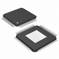
MAX4814EECB+ Maxim Integrated Products, MAX4814EECB+ Datasheet

MAX4814EECB+
Specifications of MAX4814EECB+
Related parts for MAX4814EECB+
MAX4814EECB+ Summary of contents
Page 1
... Compact 64-Pin, 10mm x 10mm TQFP Package C interface or o Optimized Layout to Support 4:4 or 2:8 Configuration with Two Devices Applications PART MAX4814EECB+ -40°C to +85°C + Denotes a lead-free package Exposed paddle. Pin Configuration appears at end of data sheet. Typical I 4.5V TO 5.5V 0.1μF MODE ...
Page 2
DVI/HDMI 2:4 Low-Frequency Fanout Switch ABSOLUTE MAXIMUM RATINGS (Voltages referenced to GND. Note 1 A_, B_, SW_, EFN..........................................-0.3V to +6.0V DD All Other Pins (except GND).........................-0. Continuous Current, A_, B_ ..............................................±60mA Continuous Current GND...................................±100mA ...
Page 3
DVI/HDMI 2:4 Low-Frequency Fanout Switch ELECTRICAL CHARACTERISTICS (continued +5V ±10 -40°C to +85°C, unless otherwise noted. Typical values are PARAMETER ANALOG SWITCHES On-Resistance Standard Switches: A[1], A[2], A[3], B[1], B[2], B[3] On-Resistance-Flatness ...
Page 4
DVI/HDMI 2:4 Low-Frequency Fanout Switch ELECTRICAL CHARACTERISTICS (continued +5V ±10 -40°C to +85°C, unless otherwise noted. Typical values are PARAMETER High Period of the SCL Clock Setup Time for a Repeated START ...
Page 5
DVI/HDMI 2:4 Low-Frequency Fanout Switch + MAX4814E 50Ω GND MEASUREMENTS ARE STANDARDIZED AGAINST SHORTS AT IC TERMINALS. OFF-ISOLATION IS MEASURED BETWEEN SW_ AND "OFF" TERMINAL ON EACH SWITCH. ON-LOSS IS MEASURED BETWEEN SW_ AND ...
Page 6
DVI/HDMI 2:4 Low-Frequency Fanout Switch (V = +5V +25°C, unless otherwise noted ON-RESISTANCE 5.0V DD ...
Page 7
DVI/HDMI 2:4 Low-Frequency Fanout Switch PIN NAME 1, 16, 24, 25, 33, 48, 56, 57 GND 2, 15, 34 I.C. 3 A[0] 4 A[1] 5 A[2] 6 A[ 17, 32, 40, 41, 49 ...
Page 8
DVI/HDMI 2:4 Low-Frequency Fanout Switch PIN NAME 45 SW1[1] 46 SW1[0] 47 N.C. 51 SW0[4] 52 SW0[3] 53 SW0[2] 54 SW0[1] 55 SW0[0] 58 DA0/DO0 59 DA1/DO1 60 DA2/DO2 61 DB0/DO3 62 DB1 63 DB2 EP EP Detailed Description The ...
Page 9
DVI/HDMI 2:4 Low-Frequency Fanout Switch GND MODE becomes input DA1, DA2/DO2 becomes input DA2, and DB0/DO3 becomes input DB0. Inputs DB1 and DB2 are enabled. In mode 0, the direct-control inputs DA_ and DB_ are used ...
Page 10
DVI/HDMI 2:4 Low-Frequency Fanout Switch DA1 select the connections of switch A to switch SW_ and inputs DB0 and DB1. Select the connections of switch B to SW_. See Table 3a for the pin configuration and Table 3b for a ...
Page 11
DVI/HDMI 2:4 Low-Frequency Fanout Switch Table 3a. Input/Output Configurations for DA_, DB_, and DO_ MODE DA0/DO0 0 DA0, Input 1 DO0, Output DO1, Output Table 3b. Mode 0 Direct-Control Configurations PIN CONNECTION DA2 0 Bank A switches are disabled 1 ...
Page 12
DVI/HDMI 2:4 Low-Frequency Fanout Switch 2 Table Register R1 (0X01) to DO_ Mapping PIN MODE BIT 7 BIT 6 1 — — 1 — — 1 — — 1 — — 1 — — 1 — — ...
Page 13
DVI/HDMI 2:4 Low-Frequency Fanout Switch Table 6. Switch Selection Truth Table DA_, DB_ INPUTS/REGISTER R0 BITS DB2/ DB1/ DB0/ DA2/ BBEN BBSEL1 BBSEL0 BAEN ...
Page 14
DVI/HDMI 2:4 Low-Frequency Fanout Switch SDA SCL t HD, STA CONDITION Figure 4. 2-Wire Interface Timing Diagram 2 MODE = CONTROL 3-STATE CONTROL MAX4814E SETS 3 ...
Page 15
DVI/HDMI 2:4 Low-Frequency Fanout Switch TOP VIEW EFN 50 SW0[4] 51 SW0[3] 52 SW0[2] 53 SW0[1] 54 SW0[0] 55 GND 56 GND 57 DA0/DO0 58 DA1/DO1 59 DA2/DO2 60 DB0/DO3 61 DB1 62 DB2 ...
Page 16
DVI/HDMI 2:4 Low-Frequency Fanout Switch (The package drawing(s) in this data sheet may not reflect the most current specifications. For the latest package outline information www.maxim-ic.com/packages.) 16 ______________________________________________________________________________________ Package Information PACKAGE OUTLINE, 64L TQFP, 10x10x1.0mm EP OPTION 1 ...
Page 17
... Maxim cannot assume responsibility for use of any circuitry other than circuitry entirely embodied in a Maxim product. No circuit patent licenses are implied. Maxim reserves the right to change the circuitry and specifications without notice at any time. Maxim Integrated Products, 120 San Gabriel Drive, Sunnyvale, CA 94086 408-737-7600 ____________________ 17 © 2007 Maxim Integrated Products ...


