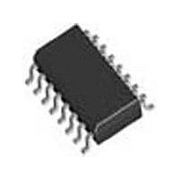
LTC1235CS Linear Technology, LTC1235CS Datasheet - Page 13

LTC1235CS
Manufacturer Part Number
LTC1235CS
Description
Manufacturer
Linear Technology
Datasheet
1.LTC1235CS.pdf
(16 pages)
Specifications of LTC1235CS
Number Of Elements
1
Monitored Voltage 1 (typ)
4.65V
Battery Backup Switching
Yes
Watchdog Timer
Yes
Chip Enable Signals
Yes
Reset Active Time
280ms
Manual Reset
Yes
Package Type
SOL
Operating Supply Voltage (min)
4.75V
Operating Supply Voltage (max)
5.5V
Reset Threshold Voltage (max)
4.75V
Reset Threshold Voltage (min)
4.5V
Power Dissipation
500mW
Operating Temp Range
0C to 70C
Operating Temperature Classification
Commercial
Power Fail Detection
Yes
Mounting
Surface Mount
Pin Count
16
Supply Current
1.5mA
Lead Free Status / Rohs Status
Not Compliant
Available stocks
Company
Part Number
Manufacturer
Quantity
Price
Part Number:
LTC1235CS
Manufacturer:
LINEAR/凌特
Quantity:
20 000
Part Number:
LTC1235CS#TRPBF
Manufacturer:
LTNEAR
Quantity:
20 000
Part Number:
LTC1235CSW
Manufacturer:
LINEAR/凌特
Quantity:
20 000
Part Number:
LTC1235CSW#PBF
Manufacturer:
LINEAR/凌特
Quantity:
20 000
Part Number:
LTC1235CSW#TR
Manufacturer:
LT/凌特
Quantity:
20 000
APPLICATIONS INFORMATION
The 10.7ms allows enough time to execute shut-down
procedure for microprocessor and 831mV of hysteresis
would prevent PFO from going low due to the noise of V
Example 2: The circuit in Figure 9 can be used to mea-
sure the regulated 5V supply to provide early warning of
power failure. Because of variations in the PFI threshold,
this circuit requires adjustment to ensure that the PFI
comparator trips before the reset threshold is reached.
Adjust R5 such that the PFO output goes low when the
V
Monitoring the Status of the Battery
C3 can also monitor the status of the memory backup
battery (Figure 10). If desired, the CE OUT can be used to
apply a test load to the battery. Since CE OUT is forced high
in battery backup mode, the test load will not be applied
to the battery while it is in use, even if the microprocessor
is not powered.
Watchdog Timer
The LTC1235 provides a watchdog timer function to monitor
the activity of the microprocessor. If the microprocessor
does not toggle the Watchdog Input (WDI) within the
time-out period, the reset outputs are forced to active
states for a minimum of 140ms. The watchdog time-out
period is fi xed at 1.0 second minimum on the LTC1235.
This time-out period provides adequate time for many
systems to service the watchdog timer immediately after
a reset. Figure 11 shows the timing diagram of watchdog
CC
supply reaches the desired level (e.g., 4.85V).
V
RESET
CC
WDO
WDI
= 5V
t1
Figure 11. Watchdog Time-out Period and Reset Active Time
t2
IN
.
t1
time-out period and reset active time. The watchdog time-
out period is restarted as soon as the reset outputs are
inactive. When either a high-to-low or low-to-high transi-
tion occurs at the WDI pin prior to time-out, the watchdog
time is reset and begins to time out again. To ensure the
watchdog time does not time out, either a high-to-low or
low-to-high transition on the WDI pin must occur at or
less than the minimum time-out period. If the input to the
WDI pin remains either high or low, reset pulses will be
issued every 1.6 seconds typically. The watchdog timer
can be deactivated by fl oating the WDI pin. The timer
is also disabled when V
threshold or V
The Watchdog Output, WDO, goes low if the watchdog timer
is allowed to time out and remains low until set high by the
next transition on the WDI pin. WDO is also set high when
V
t1 = RESET ACTIVE TIME
t2 = WATCHDOG TIME-OUT PERIOD
CC
Figure 10. Backup Battery Monitor with Optional Test Load
falls below the reset voltage threshold or V
+3V
t2
OPTIONAL TEST LOAD
BATT
R1
1M
RL 20k
R2
1M
.
t1
PFI
PFI
V
CE OUT
BATT
CC
LTC1235
+5V
falls below the reset voltage
V
CC
BACKUP
GND
CE IN
PFO
1235 F11
LTC1235
LOW BATTERY SIGNAL
TO μP I/O PIN
TO μP I/O PIN
BATT
1235 F10
13
.
1235fa


