HMMC-5618 Avago Technologies US Inc., HMMC-5618 Datasheet

HMMC-5618

Manufacturer Part Number
HMMC-5618
Description
Manufacturer
Avago Technologies US Inc.
Type
Power Amplifierr
Datasheet

Specifications of HMMC-5618

Number Of Channels
1
Frequency (max)
20GHz
Output Power
18@20000MHzdBm
Power Supply Requirement
Single
Single Supply Voltage (min)
3V
Single Supply Voltage (typ)
5V
Single Supply Voltage (max)
5.5V
Dual Supply Voltage (min)
Not RequiredV
Dual Supply Voltage (typ)
Not RequiredV
Dual Supply Voltage (max)
Not RequiredV
Supply Current
140@5VmA
Operating Temperature Classification
Industrial
Operating Temp Range
-55C to 100C
Mounting
Surface Mount
Lead Free Status / Rohs Status
Compliant

Available stocks

Company
Part Number
Manufacturer
Quantity
Price
Part Number:
HMMC-5618
Manufacturer:
AGILENT
Quantity:
20 000
Description
The HMMC-5618 6–20 GHz
MMIC is an efficient two–stage
medium-power amplifier that is
designed to be used as a cascad-
able intermediate gain block for
EW applications. In communica-
tion systems, it can be used as
an amplifier for a local oscillator
or as a transmit amplifier. It is
fabricated using a PHEMT inte-
grated circuit structure that
provides exceptional efficiency
and flat gain performance. Dur-
ing typical operation, with a sin-
gle 5–volt DC power supply,
each gain stage is biased for
Class–A operation for optimal
power output with minimal dis-
tortion. The RF input and RF
output has matching circuitry
for use in 50 ohm environments.
The backside of the chip is both
RF and DC ground. This helps
simplify the assembly process
and reduces assembly related
performance variations and
costs.
Chip Size:
Chip Size Tolerance:
Chip Thickness:
Pad Dimensions:
Absolute Maximum Ratings
Notes:
1. Absolute maximum ratings for continuous operation unless otherwise noted.
2. Operating at this power level for extended (continuous) periods is not recommended.
3. Refer to DC Specifications/Physical Properties table for de–rating information.
Symbol
V
V
V
I
I
P
T
T
T
T
D1
D2
Agilent HMMC-5618
6–20 GHz Medium Power
Amplifier
Data Sheet
ch
A
st
max
D1
G1
G2
in
,V
D2
920
127
80
10 m ( 0.4 mils)
Parameters/Conditions
Drain Supply Voltage
Optional Gate Supply Voltage
Drain Supply Current
RF Input Power
Channel Temperature
Backside Ambient Temperature
Storage Temperature
Max. Assembly Temperature
80 m (3.2
920 m (36.2
15 m (5.0
[2]
3.2 mils)
0.6 mils)
36.2 mils)
[3]
[1]
Features
•High Efficiency:
•Output Power, P
•High Gain:
•Flat Gain Response:
•Low Input/Output VSWR:
• Single Supply Bias
18 dBm Typical
14 dB Typical
<1.7:1 Typical
5 volts (@ 115 mA typ.)
with Optional Gate Bias
11% @ P
0.5 dB Typical
-1dB
Min.
10
55
65
5
Typical
-1dB
Max.
+100
+150
:
160
300
5.5
+1
+1
70
84
20
Units
Volts
Volts
Volts
dBm
mA
mA
C
C
C
C
1

Related parts for HMMC-5618

HMMC-5618 Summary of contents

Page 1

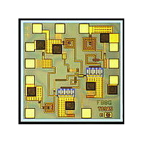
... Chip Size: Chip Size Tolerance: Chip Thickness: Description Pad Dimensions: The HMMC-5618 6–20 GHz MMIC is an efficient two–stage medium-power amplifier that is designed to be used as a cascad- able intermediate gain block for EW applications. In communica- tion systems, it can be used as an amplifier for a local oscillator transmit amplifier ...

Page 2

DC Specifications/Physical Properties Symbol Parameters/Conditions V ,V Drain Supply Voltage D1 D2 Stage–One Drain Supply Current =5V, V =Open ( or Ground Stage–Two Drain Supply Current =5V, V =Open ( or Ground) ...

Page 3

... Applications The HMMC-5618 is a GaAs MMIC medium-power amplifier designed for optimum Class–A efficiency and flat gain perfor- mance from 6 GHz to 20 GHz. It has applications as a cascadable gain stage for EW amplifier, buffer stages, LO–port driver, phased–array radar, and trans- mitter amplifiers used in com- mercial communication systems ...

Page 4

V =5.0V =Open Gain V =3. =5. Spec Range (5 GHz) 5 Isolation Frequency (GHz) Figure 2. Gain and Isolation versus Frequency ...

Page 5

V =V =5.0V =Open Spec Range (5.9–20 GHz) 15 Gain Wafer-Probed 10 Measurements Includes 0.2nH wire inductance 5 Isolation Frequency (GHz) Figure 4. Effects of Input/Output Bond Wire ...

Page 6

To V Power Supply DD 800 pF Short Bond Wires RF INPUT .2nH Bond Wire Inductance (10 mils) (a) Assembly for single drain–bias operation. 920 IN 530 0 6 Chip Capacitor (100 pF) Locate near MMIC Gold Plated Shim (Optional) ...

Page 7

This data sheet contains a variety of typical and guaranteed performance data. The information supplied should not be interpreted as a complete list of circuit specifications. In this data sheet the term typical refers to the 50th per- centile performance. ...

Page 8

8 ...

Related keywords