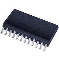
CS5523-AS Cirrus Logic Inc, CS5523-AS Datasheet - Page 37

CS5523-AS
Manufacturer Part Number
CS5523-AS
Description
ADC (A/D Converters) 4-Ch 16-Bit Delta Sigma ADC
Manufacturer
Cirrus Logic Inc
Datasheet
1.CS5521-ASZ.pdf
(56 pages)
Specifications of CS5523-AS
Architecture
Delta-Sigma
Conversion Rate
0.617 KSPs
Input Type
Voltage
Maximum Power Dissipation
500 mW
Maximum Operating Temperature
+ 85 C
Mounting Style
SMD/SMT
Package / Case
SOIC-8
Minimum Operating Temperature
- 40 C
Lead Free Status / Rohs Status
No
Available stocks
Company
Part Number
Manufacturer
Quantity
Price
Company:
Part Number:
CS5523-AS
Manufacturer:
HIT
Quantity:
1 200
Part Number:
CS5523-AS
Manufacturer:
CIRRUSLOGIC
Quantity:
20 000
Part Number:
CS5523-ASZ
Manufacturer:
CIRRUSLOGIC
Quantity:
20 000
1.4.1.5 Repeated Multiple-Setup Conversions
without Wait
(LP = 1 MC = 1 RC = 0)
In this conversion mode, the ADC will repeatedly
perform conversions, referencing multiple Setups.
The CSRP bits in the command word are ignored in
this mode. Instead, the Depth Pointer (DP3-DP0)
bits in the Configuration Register are accessed to
determine the number of Setups to reference when
collecting the data. The number of Setups refer-
enced will be equal to (DP3-DP0) + 1, and will be
accessed in order, beginning with Setup1. Note that
in this mode, the part will continually perform con-
versions, looping back to Setup1 when finished
with each set, and the user need not read every con-
version set as it becomes available. The SDO line
rises and falls to indicate the availability of new
conversion data sets. When new data is available,
the current conversion data set will be lost, or in the
case that the user has only read a part of the conver-
sion set, the remainder of the conversion set will be
corrupted.
To perform repeated, multiple-Setup conversions
with no wait, the MC bit must be set to '1', the LP
bit must be set to '1', and the RC bit must be set to
'0' in the Configuration Register. Then, the 8-bit
command word to start a conversion must be sent
to the converter. Because the CSRP bits of the
command word are ignored in this mode, a "start
convert" command referencing any of the available
Setups will begin the conversions. The ADC will
then perform conversions using the appropriate
number of Setups (as dictated by the DP bits in the
Configuration Register), beginning with Setup1.
The SDO line will fall after the final conversion to
indicate that the data is ready. Eight SCLKs, plus
24 SCLKs for each Setup referenced are required to
read the conversion words from the data FIFO. The
first 8 SCLKs are used to clear the SDO flag. Ev-
ery 24 bits thereafter consist of the data words of
each Setup that was referenced, until all of the data
DS317F8
has been read from the part. If, during the first 8
SCLKs, "00000000" is provided on SDI, the con-
verter will remain in this conversion mode, and
continue to perform conversions on the desired
number of Setups. To exit this conversion mode,
"1111 1111" must be provided on SDI during the
first 8 SCLKs. If the user decides to exit, 24 more
SCLKs for each referenced Setup are required to
read the final conversion data set from the FIFO
and return to command mode.
1.4.1.6 Repeated Multiple-Setup Conversions
with Wait
(LP = 1 MC = 1 RC = 1)
In this conversion mode, the ADC will repeatedly
perform conversions, referencing multiple Setups.
The CSRP bits in the command word are ignored in
this mode. Instead, the Depth Pointer (DP3-DP0)
bits in the Configuration Register are accessed to
determine the number of Setups to reference when
collecting the data. The number of Setups refer-
enced will be equal to (DP3-DP0) + 1, and will be
accessed in order, beginning with Setup1. Note that
in this mode, every conversion data set must be
read. The part will wait for the current conversion
data set to be read before performing the next set of
conversions.
To perform repeated, multiple-Setup conversions
with wait, the MC bit must be set to '1', the LP bit
must be set to '1', and the RC bit must be set to '1'
in the Configuration Register. Then, the 8-bit com-
mand word to start a conversion must be sent to the
converter. Because the CSRP bits of the command
word are ignored in this mode, a "start convert"
command referencing any of the available Setups
will begin the conversions. The ADC will then per-
form conversions using the appropriate number of
Setups (as dictated by the DP bits in the Configura-
tion Register), beginning with Setup1. The SDO
line will fall after the final conversion to indicate
that the data is ready.
CS5521/22/23/24/28
Eight SCLKs, plus 24
37


