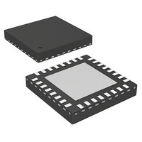
AS5215OM-HMFP austriamicrosystems, AS5215OM-HMFP Datasheet - Page 12

AS5215OM-HMFP
Manufacturer Part Number
AS5215OM-HMFP
Description
IC ENCODER PROG 32-VQFN
Manufacturer
austriamicrosystems
Series
-r
Type
Linear, Rotary Encoder - Programmabler
Datasheets
1.AS5215OM-HMFP-500.pdf
(26 pages)
2.AS5215OM-HMFP-500.pdf
(2 pages)
3.AS5215OM-HMFP-500.pdf
(2 pages)
Specifications of AS5215OM-HMFP
Mfg Application Notes
AS5000 Series Magnet Selection Guide AS5000 Series Magnets for Extended Vertical Range
Sensing Range
20mT ~ 80mT
Voltage - Supply
4.5 V ~ 5.5 V
Current - Supply
28mA
Current - Output (max)
-
Output Type
Analog
Features
Programmable
Operating Temperature
-40°C ~ 150°C
Package / Case
32-VQFN Exposed Pad
Lead Free Status / Rohs Status
Lead free / RoHS Compliant
Other names
AS5215-HQFT
AS5215-HQFT
AS5215-HQFT-OM
AS5215-HQFT
AS5215-HQFT-OM
AS5215
Datasheet - D e t a i l e d D e s c r i p t i o n
7.1.3 Axial Distance (Airgap)
Figure 7. Sinusoidal Magnetic Field Generated by the Rotating Magnet
B
vertical
field
0
360º
The recommended magnetic field, measured at the chip surface on a radius equal to the Hall sensor array radius (typ 1mm) should be within a
certain range. This range lies between 45 and 75mT or between 20 and 80mT, depending on the encoder product.
Linear position sensors are more sensitive as they use weaker magnets. The allowed magnetic range lies typically between 5 and 60mT.
7.1.4 Angle Error vs. Radial and Axial Misalignment
The angle error is the deviation of the actual angle vs. the angle measured by the encoder. There are several factors in the chip itself that
contribute to this error, mainly offset and gain matching of the amplifiers in the analog signal path. On the other hand, there is the nonlinearity of
the signals coming from the Hall sensors, caused by misalignment of the magnet and imperfections in the magnetic material.
Ideally, the Hall sensor signals should be sinusoidal, with equal peak amplitude of each signal. This can be maintained, as long as all Hall
elements are within the linear range of the magnetic field Bz
(see Figure
5).
7.1.5 Mounting the Magnet
Generally, for on-axis rotation angle measurement, the magnet must be mounted centered over the IC package. However, the material of the
shaft into which the magnet is mounted, is also of big importance.
Magnetic materials in the vicinity of the magnet will distort or weaken the magnetic field being picked up by the Hall elements and cause
additional errors in the angular output of the sensor.
Figure 8. Magnetic Field Lines in Air
Figure 8
shows the ideal case with the magnet in air. No magnetic materials are anywhere nearby.
www.austriamicrosystems.com/AS5215
Revision 1.11
12 - 26


