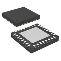
AS5215OM-HMFP austriamicrosystems, AS5215OM-HMFP Datasheet - Page 8

AS5215OM-HMFP
Manufacturer Part Number
AS5215OM-HMFP
Description
IC ENCODER PROG 32-VQFN
Manufacturer
austriamicrosystems
Series
-r
Type
Linear, Rotary Encoder - Programmabler
Datasheets
1.AS5215OM-HMFP-500.pdf
(26 pages)
2.AS5215OM-HMFP-500.pdf
(2 pages)
3.AS5215OM-HMFP-500.pdf
(2 pages)
Specifications of AS5215OM-HMFP
Mfg Application Notes
AS5000 Series Magnet Selection Guide AS5000 Series Magnets for Extended Vertical Range
Sensing Range
20mT ~ 80mT
Voltage - Supply
4.5 V ~ 5.5 V
Current - Supply
28mA
Current - Output (max)
-
Output Type
Analog
Features
Programmable
Operating Temperature
-40°C ~ 150°C
Package / Case
32-VQFN Exposed Pad
Lead Free Status / Rohs Status
Lead free / RoHS Compliant
Other names
AS5215-HQFT
AS5215-HQFT
AS5215-HQFT-OM
AS5215-HQFT
AS5215-HQFT-OM
AS5215
Datasheet - D e t a i l e d D e s c r i p t i o n
7 Detailed Description
The AS5215 is a redundant rotary encoder sensor front end. Based on an integrated Hall element array, the angular position of a simple two-pole
magnet is translated into analog output voltages. The angle information is provided by means of sine and cosine voltages. This approach gives
maximum flexibility in system design, as it can be directly integrated into existing architectures and optimized for various applications in terms of
speed and accuracy.
With two independent dies in one package, the device offers true redundancy. Usually the bottom die, which is exposed to slightly less magnetic
field is employed for plausibility check.
An SSI (SPI standard) protocol is implemented for internal test access to the different circuit blocks and for signal path configuration.
A One Time Programmable register block (OTP) allows the customer to adjust the signal path gain to adjust for different mechanical constraints
and magnetic field strengths. Furthermore, for internal use, the test mode can be enabled and the system oscillator is trimmable, DC offset of the
output signal can be set to either 1.5V or 2.5V. A unique chip ID is stored to ensure traceability.
For operating point control, a band gap circuit is implemented together with a central bias block to distribute all reference bias currents for the
analog signal conditioning. The digital signal part is based on a 2MHz system, CLK derived via. divider from a 4MHz system oscillator.
Figure 3. Typical Arrangement of AS5215 and Magnet
7.1 Magnet Diameter and Vertical Distance
Note: Following is just an abstract taken from the elaborate application note on the Magnet.
7.1.1 The Linear Range
The Hall elements used in the AS5000-series sensor ICs are sensitive to the magnetic field component Bz, which is the magnetic field vertical to
the chip surface.
an axial distance of 1mm between magnet and IC.
The highest magnetic field occurs at the north and south poles, which are located close to the edge of the magnet, at ~2.8mm radius
5). Following the poles towards the center of the magnet, the Bz field decreases very linearly within a radius of ~1.6mm. This linear range is the
operating range of the magnet with respect to the Hall sensor array on the chip. For best performance, the Hall elements should always be within
this linear range.
www.austriamicrosystems.com/AS5215
For more detailed information, please visit our homepage
Application Notes
Figure 4
shows a 3-dimensional graph of the Bz field across the surface of a 6mm diameter, cylindrical NdFeB N35H magnet at
www.austriamicrosystems.com → Magnetic Rotary Encoders
Revision 1.11
→ Magnet
(see Figure
8 - 26


