U4082B-MFLG3G Atmel, U4082B-MFLG3G Datasheet - Page 26

U4082B-MFLG3G
Manufacturer Part Number
U4082B-MFLG3G
Description
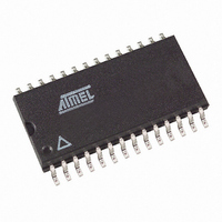
IC VOICE-SWITCH SPKR CIRC 28SOIC
Manufacturer
Atmel
Datasheet
1.U4082B-MFLG.pdf
(30 pages)
Specifications of U4082B-MFLG3G
Function
Voice-Switched Speakerphone
Number Of Circuits
1
Voltage - Supply
3.5 V ~ 6.5 V
Current - Supply
5.5mA
Power (watts)
520W
Operating Temperature
-20°C ~ 60°C
Mounting Type
Surface Mount
Package / Case
28-SOIC (7.5mm Width)
Includes
Background Noise Monitor, Chip Disable, Dial Tone Detection, MUTE
Lead Free Status / RoHS Status
Lead free / RoHS Compliant
Interface
-
Available stocks
Company
Part Number
Manufacturer
Quantity
Price
Company:
Part Number:
U4082B-MFLG3G
Manufacturer:
ATMEL
Quantity:
560
26
U4082B
This equation defines the line voltage at Tip/Ring necessary to switch comparator C2 in the
presence of a microphone voltage. The highest V
(G
V
At idle, where the gain of the two attenuators is –20 dB (0.1V/V), equations 6 and 10 yield the
same result:
V
Equations 7, 11, and 12 define the thresholds for switching, and are represented in
The "M" terms are the slopes of the lines (0.52, 0.024, and 0.0019) which are the coefficients of
the three equations. The M
the microphone signal level necessary to switch to transmit in the presence of a given receive
signal level. The M
idle condition, and defines the threshold level on one side (transmit or receive) necessary to
overcome noise on the other.
Figure 8-4.
Some comments on the graph (see
G
L
M
• Acoustic coupling and side tone coupling were not included in equations 7 and 12. Those
• The M
AC(MAX)
T
= 840 × V
couplings will affect the actual performance of the final speakerphone due to their interaction
with speech at the microphone and the receive signal coming in at Tip/Ring. The effects of
those couplings are difficult to predict due to their associated phase shifts and frequency
response. In some cases the coupling signal will add, and other times subtract from the
incoming signal. The physical design of the speakerphone enclosure, as well as the specific
phone line to which it is connected, will affect the acoustic and side tone couplings,
respectively.
found from the following equation:
= 0.024 × V
= +6.0 dB). Using the typical numbers for equation 10 yields:
=
R
line helps define the maximum acoustic coupling allowed in a system, which can be
------------------------------------
2
M
Switching Thresholds
(or V
L
R
R
3
1
T
M
G
line represents the transmit to receive threshold. The M
= 0.0019 × V
MA
R
V
M
line represents the receive to transmit threshold, in that it defines
(13)
L
)
Figure
(11)
M
R
8-4):
L
occurs when the circuit is in transmit mode
M
I
(12)
V
M
L
T
I
line represents the
4743D–CORD–03/06
Figure 8-4


