U4082B-MFLG3G Atmel, U4082B-MFLG3G Datasheet - Page 27
U4082B-MFLG3G
Manufacturer Part Number
U4082B-MFLG3G
Description
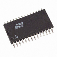
IC VOICE-SWITCH SPKR CIRC 28SOIC
Manufacturer
Atmel
Datasheet
1.U4082B-MFLG.pdf
(30 pages)
Specifications of U4082B-MFLG3G
Function
Voice-Switched Speakerphone
Number Of Circuits
1
Voltage - Supply
3.5 V ~ 6.5 V
Current - Supply
5.5mA
Power (watts)
520W
Operating Temperature
-20°C ~ 60°C
Mounting Type
Surface Mount
Package / Case
28-SOIC (7.5mm Width)
Includes
Background Noise Monitor, Chip Disable, Dial Tone Detection, MUTE
Lead Free Status / RoHS Status
Lead free / RoHS Compliant
Interface
-
Available stocks
Company
Part Number
Manufacturer
Quantity
Price
Company:

Part Number:
U4082B-MFLG3G
Manufacturer:
ATMEL
Quantity:
560


9. Application Information
9.1
9.2
4743D–CORD–03/06
Dial Tone Detector
Background Noise Monitors
Equation 13 is independent of the volume control setting. Conversely, the acoustic coupling of a
designed system helps determine the minimum slope of that line. Using the component values
of
ever, that an acoustic coupling loss of 40 dB is desirable.
Using the component values of
of 0 dB. Experience has shown, however, that a minimum of 6.0 dB loss is preferable.
The above equations can be used to determine the resistor values for the level detector inputs.
Equation 6 can be used to determine the R
the R
resistor and coupling capacitor at each level detector input. The magnitude of each RC's imped-
ance should be kept within the range of 2.0 k to 15 k in the voice band (due to the typical
signal levels present) to obtain the best performance from the level detectors. The specific R
and C at each location will determine the frequency response of that level detector.
The threshold for the dial tone detector is internally set at 15 mV (10 mVrms) below V
ure 3-3 on page
The resistor value is calculated from:
where V
resistor from V
where V is the amount of the threshold increase.
For testing or circuit analysis purposes, the transmit or receive attenuators can be set to the “on”
position by disabling the background noise monitors and applying a signal so as to activate the
level detectors. Grounding the CPR pin will disable the receive background noise monitor,
thereby indicating the “presence of speech” to the attenuator control block. Grounding CPT does
the same for the transmit path.
Additionally, the receive background noise monitor is automatically disabled by the dial tone
detector whenever the receive signal exceeds the detector's threshold.
G
R
R
• The M
ST
Figure 1-2 on page 2
=
=
can be found using the following equation:
=
10 k
10 k
1
-R
----------------------------------- -
2
B
2
T
is the voltage at pin 15, and V is the amount of threshold reduction. By connecting a
ratio. In
------- - 1
V
------------------- - 1
V
R
line helps define the maximum side tone coupling (G
V
S
B
R
2
–
4
–
V
S
V
G
to RI, the threshold can be increased. The resistor value is calculated from:
B
7). That threshold can be reduced by connecting a resistor from RI to ground.
FO
–
Figure 8-3 on page
in equation 13 yields a G
(14)
Figure 1-2 on page 2
23, R
1
1
-R
-R
3
4
ratio, and equation 10 can be used to determine
each represent the combined impedance of the
AC(MAX)
in equation 14 yields a maximum side tone
of –37 dB. Experience has shown, how-
ST
) allowed in the system. G
U4082B
B
(see
ST
Fig-
27
Related parts for U4082B-MFLG3G
Image
Part Number
Description
Manufacturer
Datasheet
Request
R

Part Number:
Description:
Low-Voltage Voice-Switched IC for Hands-Free Operation
Manufacturer:
ATMEL Corporation
Datasheet:

Part Number:
Description:
IC VOICE-SWITCH SPKR CIRC 28SOIC
Manufacturer:
Atmel
Datasheet:

Part Number:
Description:
WiFi / 802.11 Modules & Development Tools Voice Switched Circuit
Manufacturer:
Atmel
Datasheet:

Part Number:
Description:
DEV KIT FOR AVR/AVR32
Manufacturer:
Atmel
Datasheet:
Part Number:
Description:
INTERVAL AND WIPE/WASH WIPER CONTROL IC WITH DELAY
Manufacturer:
ATMEL Corporation
Datasheet:
Part Number:
Description:
MONOLITHIC INTEGRATED FEATUREPHONE CIRCUIT
Manufacturer:
ATMEL Corporation
Datasheet:
Part Number:
Description:
AM-FM Receiver IC U4255BM-M
Manufacturer:
ATMEL Corporation
Datasheet:
Part Number:
Description:
Monolithic Integrated Feature Phone Circuit
Manufacturer:
ATMEL Corporation
Datasheet:
Part Number:
Description:
Multistandard Video-IF and Quasi Parallel Sound Processing
Manufacturer:
ATMEL Corporation
Datasheet:
Part Number:
Description:
High-performance EE PLD
Manufacturer:
ATMEL Corporation
Datasheet:
Part Number:
Description:
8-bit Flash Microcontroller
Manufacturer:
ATMEL Corporation
Datasheet:
Part Number:
Description:
2-Wire Serial EEPROM
Manufacturer:
ATMEL Corporation
Datasheet: