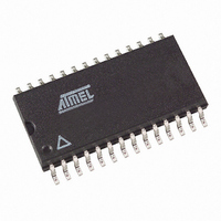
U4082B-MFLG3G Atmel, U4082B-MFLG3G Datasheet - Page 7

U4082B-MFLG3G
Manufacturer Part Number
U4082B-MFLG3G
Description
IC VOICE-SWITCH SPKR CIRC 28SOIC
Manufacturer
Atmel
Datasheet
1.U4082B-MFLG.pdf
(30 pages)
Specifications of U4082B-MFLG3G
Function
Voice-Switched Speakerphone
Number Of Circuits
1
Voltage - Supply
3.5 V ~ 6.5 V
Current - Supply
5.5mA
Power (watts)
520W
Operating Temperature
-20°C ~ 60°C
Mounting Type
Surface Mount
Package / Case
28-SOIC (7.5mm Width)
Includes
Background Noise Monitor, Chip Disable, Dial Tone Detection, MUTE
Lead Free Status / RoHS Status
Lead free / RoHS Compliant
Interface
-
Available stocks
Company
Part Number
Manufacturer
Quantity
Price
Company:
Part Number:
U4082B-MFLG3G
Manufacturer:
ATMEL
Quantity:
560
3.5
3.6
3.7
4743D–CORD–03/06
Volume Control
Dial Tone Detector
AGC
The volume control input at VCI (pin 13) is sensed as a voltage with respect to V
attenuators in receive mode only and has no effect during idle or transmit mode.
In receive mode, the attenuator receive gain, G
–46 dB under the condition that VCI = V
reduced
however, remains constant. Voltage deviation at VCI changes the voltage at C
controls the attenuators (see section
The volume control setting does not affect the maximum attenuator input signal at which notice-
able distortion occurs.
The bias current at VCI is typically –60 nA. It does not vary significantly with the VCI voltage or
supply voltage V
The dial tone detector is a comparator with one side connected to the receive input (RI) and the
other to V
signal is greater than 15 mV (10 mVrms), the comparator's output will change, disabling the
receive idle mode. The receive attenuator will then be at a setting determined mainly by the vol-
ume control.
This circuit prevents the dial tone (which would be considered as continuous noise) from fading
away as the circuit would have the tendency to switch to idle mode. By disabling the receive idle
mode, the dial tone remains at the normally-expected full level.
Figure 3-3.
The AGC circuit affects the circuit only in receive mode, and only when the supply voltage is less
than 3.5V. As V
page
gains remains constant.
The purpose of this feature is to reduce the power (and current) used by the speaker when a
line-powered speakerphone is connected to a long line where the available power is limited. By
reducing the speaker power, the voltage sag at V
operation.
19. The transmit path attenuation changes such that the sum of the transmit and receive
(Figure 7-5 on page
B
with a 15 mV offset (see
Dial Tone Detector
S
S
.
< 3.5V, the gain of the receive attenuator is reduced as seen in
21
R
I
V
B
19), whereas the attenuator transmit gain is increased; their sum,
15 mV
“Attenuator Control Block” on page
Figure
To R attenuator
-
+
B
3-3). If the circuit is in idle mode, and the incoming
. When VCI < V
R
, is +6.0 dB, and attenuator transmit gain G
C4
S
is controlled, preventing possible erratic
To attenuator
B
control
, the attenuator receive gain is
8).
T
B
U4082B
, which in turn
. It affects the
Figure 7-6 on
T
is
7


