DS2180AN Maxim Integrated Products, DS2180AN Datasheet - Page 26
DS2180AN
Manufacturer Part Number
DS2180AN
Description
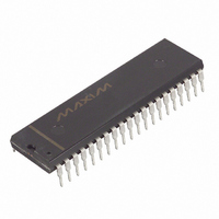
IC TRANSCEIVER T1 IND 40-DIP
Manufacturer
Maxim Integrated Products
Datasheet
1.DS2180A.pdf
(35 pages)
Specifications of DS2180AN
Function
Transceiver
Interface
T1
Number Of Circuits
1
Voltage - Supply
4.5 V ~ 5.5 V
Current - Supply
3mA
Operating Temperature
-40°C ~ 85°C
Mounting Type
Through Hole
Package / Case
40-DIP (0.600", 15.24mm)
Includes
Alarm Generation and Detection, B7 Stuffing Mode, B8ZS Mode, Error Detection and Counter, "Hardware" Mode, Transparent Mode
Lead Free Status / RoHS Status
Contains lead / RoHS non-compliant
Power (watts)
-


make it compatible with bipolar transmission techniques and inserts zero suppression codes. The bipolar
coder also supports the onboard loopback feature. Input-to-output delay of the transmitter is 10 TCLK
cycles.
RECEIVE SIDE OVERVIEW
Synchronizer
The heart of the receiver is the synchronizer monitor. This circuit serves two purposes: 1) monitoring the
incoming data stream for loss of frame or multiframe alignment, and 2) searching for new frame
alignment pattern when sync loss is detected. When sync loss is detected, the synchronizer begins an off-
line search for the new alignment; all output timing signals remain at the old alignment with the exception
of RSIGFR, which is forced low during resync. When one and only one candidate is qualified, the output
timing will move to the new alignment at the beginning of the next multiframe. One frame later, RLOS
will transition low, indicating valid sync and the resumption of the normal sync monitoring mode. Several
bits in the RCR allow tailoring of the resync algorithm by the user. These bits are described below.
Sync Time (RCR.2)
Bit RCR.2 determines the number of consecutive framing pattern bits to be qualified before SYNC is
declared. If RCR.2=1, the algorithm will validate 24 bits; if RCR.2=0, 10 bits are validated. 24-bit
testing results in superior false framing protection, while 10-bit testing minimizes reframe time (although
in either case, the synchronizer will only establish resync when one and only one candidate is found).
Resync (RCR.0)
A 0-to-1 transition of RCR.0 causes the synchronizer to search for the framing pattern sequence
immediately, regardless of the internal sync status. In order to initiate another resync command, this bit
must be cleared and then set again.
Sync Enable (RCR.1)
When RCR.1 is cleared, the receiver will initiate automatic resync if any of the following events occur: 1)
an OOF event (“out-of-frame”), or 2) carrier loss (32 consecutive 0’s appear at RPOS and RNEG). An
OOF event occurs any time that 2 of 4 F
resync circuitry is disabled; in this case, resync can only be initiated by setting RCR.0 to 1 or externally
via a low-high transition on
while
Sync Criteria (RCR.3)
193E
Bit RCR.3 determines which sync algorithm is utilized when resync is in progress (RLOS=1). In 193E
framing, when RCR.3=0, the synchronizer will lock only to the FPS pattern and will move to the new
frame and multiframe alignment after the move to the new alignment. When RCR.3=1, the new
alignment is further tested by a CRC code match. RLOS will transition low after a CRC match occurs. If
no CRC match occurs in three attempts (three multiframes), the algorithm will reset and a new search for
the framing pattern begins. It takes 9 ms for the synchronizer to check the first CRC code after the new
alignment has been loaded. Each additional CRC test takes 3 ms. Regardless of the state of RCR.3, if
more than one candidate exists after about 24 ms, the synchronizer will begin eliminating emulators by
testing their CRC codes online in order to find the true framing candidate.
193S
In 193S framing, when RCR.3=1, the synchronizer will cross check the F
help eliminate false framing candidates such as digital milliwatts. The F
RST
is low; use of RCR.1 does not affect output timing until the new alignment is located.
RST
. Note that using
T
or FPS bits are in error. When RCR.1 is set, the automatic
26 of 35
RST
to initiate resync resets the receive output timing
S
T
pattern with the F
patterns are compared to the
S
pattern to
DS2180A
Related parts for DS2180AN
Image
Part Number
Description
Manufacturer
Datasheet
Request
R

Part Number:
Description:
MAX7528KCWPMaxim Integrated Products [CMOS Dual 8-Bit Buffered Multiplying DACs]
Manufacturer:
Maxim Integrated Products
Datasheet:
Part Number:
Description:
Single +5V, fully integrated, 1.25Gbps laser diode driver.
Manufacturer:
Maxim Integrated Products
Datasheet:
Part Number:
Description:
Single +5V, fully integrated, 155Mbps laser diode driver.
Manufacturer:
Maxim Integrated Products
Datasheet:
Part Number:
Description:
VRD11/VRD10, K8 Rev F 2/3/4-Phase PWM Controllers with Integrated Dual MOSFET Drivers
Manufacturer:
Maxim Integrated Products
Datasheet:
Part Number:
Description:
Highly Integrated Level 2 SMBus Battery Chargers
Manufacturer:
Maxim Integrated Products
Datasheet:
Part Number:
Description:
Current Monitor and Accumulator with Integrated Sense Resistor; ; Temperature Range: -40°C to +85°C
Manufacturer:
Maxim Integrated Products
Part Number:
Description:
TSSOP 14/A�/RS-485 Transceivers with Integrated 100O/120O Termination Resis
Manufacturer:
Maxim Integrated Products
Part Number:
Description:
TSSOP 14/A�/RS-485 Transceivers with Integrated 100O/120O Termination Resis
Manufacturer:
Maxim Integrated Products
Part Number:
Description:
QFN 16/A�/AC-DC and DC-DC Peak-Current-Mode Converters with Integrated Step
Manufacturer:
Maxim Integrated Products
Part Number:
Description:
TDFN/A/65V, 1A, 600KHZ, SYNCHRONOUS STEP-DOWN REGULATOR WITH INTEGRATED SWI
Manufacturer:
Maxim Integrated Products
Part Number:
Description:
Integrated Temperature Controller f
Manufacturer:
Maxim Integrated Products
Part Number:
Description:
SOT23-6/I�/45MHz to 650MHz, Integrated IF VCOs with Differential Output
Manufacturer:
Maxim Integrated Products
Part Number:
Description:
SOT23-6/I�/45MHz to 650MHz, Integrated IF VCOs with Differential Output
Manufacturer:
Maxim Integrated Products
Part Number:
Description:
EVALUATION KIT/2.4GHZ TO 2.5GHZ 802.11G/B RF TRANSCEIVER WITH INTEGRATED PA
Manufacturer:
Maxim Integrated Products
Part Number:
Description:
QFN/E/DUAL PCIE/SATA HIGH SPEED SWITCH WITH INTEGRATED BIAS RESISTOR
Manufacturer:
Maxim Integrated Products
Datasheet: