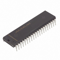
DS2180AN Maxim Integrated Products, DS2180AN Datasheet - Page 3

DS2180AN
Manufacturer Part Number
DS2180AN
Description
IC TRANSCEIVER T1 IND 40-DIP
Manufacturer
Maxim Integrated Products
Datasheet
1.DS2180A.pdf
(35 pages)
Specifications of DS2180AN
Function
Transceiver
Interface
T1
Number Of Circuits
1
Voltage - Supply
4.5 V ~ 5.5 V
Current - Supply
3mA
Operating Temperature
-40°C ~ 85°C
Mounting Type
Through Hole
Package / Case
40-DIP (0.600", 15.24mm)
Includes
Alarm Generation and Detection, B7 Stuffing Mode, B8ZS Mode, Error Detection and Counter, "Hardware" Mode, Transparent Mode
Lead Free Status / RoHS Status
Contains lead / RoHS non-compliant
Power (watts)
-
TRANSMIT PIN DESCRIPTION (40-PIN DIP ONLY) Table 1
PORT PIN DESCRIPTION (40-PIN DIP ONLY) Table 2
NOTE:
1. Multifunction pins. See “Hardware Mode Description."
PIN
PIN
10
11
12
13
14
15
16
17
18
19
1
2
3
4
5
6
7
8
9
SYMBOL
SYMBOL
TMSYNC
TCHCLK
TSIGSEL
TFSYNC
TSIGFR
TABCD
TLCLK
TLINK
SCLK
TCLK
TNEG
TSER
TPOS
TMO
SDO
INT
SDI
SPS
CS
1
1
1
1
1
TYPE
TYPE
O
O
O
O
O
O
O
O
I
I
I
I
I
I
I
I
I
I
Transmit Multiframe Sync. May be pulsed high at multiframe boundaries to
reinforce multiframe alignment or tied low, which allows internal multiframe
counter to free run.
Transmit Frame Sync. Rising edge identifies frame boundary; may be pulsed
every frame to reinforce internal frame counter or tied low (allowing TMSYNC to
establish frame and multiframe alignment).
Transmit Clock. 1.544 MHz primary clock.
Transmit Channel Clock. 192 kHz clock which identifies time slot (channel)
boundaries. Useful for parallel-to-serial conversion of channel data.
Transmit Serial Data. NRZ data input, sample on falling edge of TCLK.
Transmit Multiframe Out. Output of internal multiframe counter indicates
multiframe boundaries. 50% duty cycle.
Transmit Signaling Select. .667 kHz clock which identifies signaling frame A and
C in 193E framing. 1.33 kHz clock in 193S.
Transmit Signaling Frame. High during signaling frames, low otherwise.
Transmit ABCD Signaling. When enabled via TCR.4, sampled during channel
LSB time in signaling frames on falling edge of TCLK.
Transmit Link Data. Sampled during the F-bit time (falling edge of TCLK) of odd
frames for insertion into the outgoing data stream (193E-FDL insertion). Sampled
during the F-bit time of even frames for insertion into the outgoing data (193S-
External S-Bit insertion).
Transmit Link Clock. 4 kHz demand clock for TLINK input.
Transmit Bipolar Data Outputs. Updated on rising edge of TCLK.
Receive Alarm Interrupt. Flags host controller during alarm conditions. Active
low, open drain output.
Serial Data In. Data for onboard registers. Sampled on rising edge of SCLK.
Serial Data Out. Control and status information from onboard registers. Updated
on falling edge of SCLK, tri-stated during serial port write or when CS is high.
Chip Select. Must be low to write or read the serial port registers.
Serial Data Clock. Used to write or read the serial port registers.
Serial Port Select. Tie to V
mode.
3 of 35
DD
to select serial port. Tie to V
DESCRIPTION
DESCRIPTION
SS
to select hardware
DS2180A


