BA5416 Rohm Semiconductor, BA5416 Datasheet - Page 6
BA5416
Manufacturer Part Number
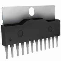
BA5416
Description
IC AMP AUDIO PWR 5.4W STER 12SIP
Manufacturer
Rohm Semiconductor
Type
Class ABr
Datasheet
1.BA5416.pdf
(10 pages)
Specifications of BA5416
Output Type
2-Channel (Stereo)
Max Output Power X Channels @ Load
5.4W x 2 @ 3 Ohm
Voltage - Supply
5 V ~ 15 V
Features
Depop, Mute, Standby, Thermal Protection
Mounting Type
Through Hole
Package / Case
12-SIP + Tab
Lead Free Status / RoHS Status
Lead free / RoHS Compliant
Available stocks
Company
Part Number
Manufacturer
Quantity
Price

Part Number:
BA5416
Manufacturer:
ROHM/罗姆
Quantity:
20 000


Audio ICs
(4) V
(5) Standby switch
(6) Filter pin
(7) Applied voltage
The Pre. GND and Pow. GND are joined at pin12, so there is a chance of crosstalk or degraded distortion
performance due to common ground impedance in the PCB pattern. In addition, the power supply capacitor
connected between V
degrade the ripple rejection and distortion. Design the PCB after referring to the application example PCB (the
recommended value for the power supply capacitor is 1000µF of greater).
The IC has built-in standby switch (pin6), so the IC can be powered on and off by a switch with low current capacity.
The on voltage V1 can be in the range 3V to V
characteristics as with conventional methods. This also increases design freedom. At normal temperatures, the
switch operates at a voltage of V1=3V or higher, but we recommend that you use it at 3.5V or higher to allow for low
temperatures. A small “pop” noise may be generated when the power is switched off using the external switch. If this
is the case, connect a capacitor of about C3=0.022µF in parallel with the switch.
Pin7 is for connection of a ripple filter. The ripple rejection can be increased somewhat by increasing the capacitance,
but this also affects the starting time, so we recommend a value in the range 100µF to 220µF. The standard starting
time is 0.8sec.
As long as the output power transistor is operated within the ASO (safe operating range Fig.9), the IC can be
operated to its absolute maximum ratings (V
recommended operating voltage range; exceeding this range will result in destruction of the IC. When the standby
switch is off, the IC is guaranteed up to V
regulation characteristics (including the capacitance of the power supply capacitor connected between V
GND) so that V
be reversed and the IC will be destroyed instantly.
CC
and GND lines
CC
is 18.0V or less (15.0V or less for the BA5416). If the IC is inserted backwards, V
CC
and GND is influenced by the PCB pattern, and common V
V1
100µ
FILTER
+
V
CC
CC
GND
Max.=24.0V, but when the standby switch is on, set the power supply
C3
S1
1.0
0.8
0.6
0.4
0.2
CC
0
18
CC
Max.=24.0V). During normal operation, operate the IC within its
12
, so the standby switch will not adversely influence circuit
1
7
SUPPLY VOLTAGE : V
GND
12
IN
ASO SAMPLE DATA
20
6
Fig.7
Fig.8
76k
8k
Start circuit
50k
Fig.9
22
Small-signal circuit
Start circuit
50k
DC(t=1sec)
Ta=25
CC
24
(V)
°C
26
BA5415A / BA5416
CC
and GND impedance may
CC
and GND will
CC
and
Related parts for BA5416
Image
Part Number
Description
Manufacturer
Datasheet
Request
R

Part Number:
Description:
Manufacturer:
Rohm Semiconductor
Datasheet:
Part Number:
Description:
Manufacturer:
Rohm Semiconductor
Datasheet:
Part Number:
Description:
Manufacturer:
Rohm Semiconductor
Datasheet:
Part Number:
Description:
Manufacturer:
Rohm Semiconductor
Datasheet:
Part Number:
Description:
Manufacturer:
Rohm Semiconductor
Datasheet:
Part Number:
Description:
Manufacturer:
Rohm Semiconductor
Datasheet:
Part Number:
Description:
Manufacturer:
Rohm Semiconductor
Datasheet:
Part Number:
Description:
Manufacturer:
Rohm Semiconductor
Datasheet:
Part Number:
Description:
Manufacturer:
Rohm Semiconductor
Datasheet:
Part Number:
Description:
Manufacturer:
Rohm Semiconductor
Datasheet:
Part Number:
Description:
Manufacturer:
Rohm Semiconductor
Datasheet:
Part Number:
Description:
Manufacturer:
Rohm Semiconductor
Datasheet:

Part Number:
Description:
DIODE SWITCH 80V 25MA SMD5 TR
Manufacturer:
Rohm Semiconductor
Datasheet: