AD813ANZ Analog Devices Inc, AD813ANZ Datasheet - Page 15

AD813ANZ
Manufacturer Part Number
AD813ANZ
Description
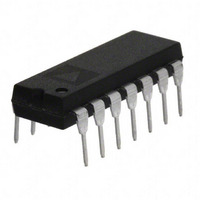
IC OPAMP TRIPLE VIDEO LP 14DIP
Manufacturer
Analog Devices Inc
Datasheet
1.AD813ARZ-14.pdf
(19 pages)
Specifications of AD813ANZ
Slew Rate
250 V/µs
Applications
Current Feedback
Number Of Circuits
3
-3db Bandwidth
100MHz
Current - Supply
4.5mA
Current - Output / Channel
50mA
Voltage - Supply, Single/dual (±)
2.4 V ~ 36 V, ±1.2 V ~ 18 V
Mounting Type
Through Hole
Package / Case
14-DIP (0.300", 7.62mm)
Gain Bandwidth
125MHz
Supply Voltage Range
2.4V To 36V
No. Of Amplifiers
3
Output Current
50mA
Amplifier Output
Single Ended
Operating Temperature Range
-40°C To +85°C
Lead Free Status / RoHS Status
Lead free / RoHS Compliant
Available stocks
Company
Part Number
Manufacturer
Quantity
Price
Company:
Part Number:
AD813ANZ
Manufacturer:
MAXIM
Quantity:
17 513
REV. B
Figure 44. Circuit of Figure 38 Driving a 510 pF Load
Capacitor, V
R
Figure 43. Response to a Large Load Capacitor at
V
Figure 42. Response to a Small Load Capacitor at
V
S
S
S
=15 )
= 15 V
–3
–3
= 5 V
9
6
3
0
9
6
3
0
100
1
1
9 0
1 0
100
0 %
5 V
S
5V
C
= 15 V (R
L
= 510pF, R
10
10
FREQUENCY – MHz
FREQUENCY – MHz
S
= 15
L
R
= 1 k , R
S
= 30
R
S
= 50
C
L
= 150pF, R
100
100
R
F
S
= R
= 0
G
S
V
G = +2
R
R
C
V
G = +2
R
R
= 30
= 750 ,
S
1 00 n s
S
F
L
L
F
L
=
= 750
= 1k
= 10pF
=
= 750
= 1k
5V
15V
1000
1000
–15–
Overload Recovery
There are three important overload conditions to consider.
They are due to: input common-mode voltage overdrive, out-
put voltage overdrive, and input current overdrive. When the
amplifier is configured for low closed-loop gains, and the input
common-mode voltage range is exceeded, the recovery time will
be very fast, typically under 30 ns. When configured for a
higher gain, and overloaded at the output, the recovery time will
also be short. For example, in a gain of +10, with 6 dB of
input overdrive, the recovery time of the AD813 is about 25 ns
(see Figure 45).
In the case of high gains with very high levels of input overdrive,
a longer recovery time will occur. For example, if the input
common-mode voltage range is exceeded in the gain of +10, the
recovery time will be on the order of 100 ns. This is primarily
due to current overloading of the input stage.
As noted in the warning under Maximum Power Dissipation, a
high level of input overdrive in a high noninverting gain circuit
can result in a large current flow in the input stage. Though this
current is internally limited to about 40 mA, its effect on the
total power dissipation may be significant.
100
10
0%
90
Figure 45. 6 dB Overload Recovery, G = +10,
(R
L
= 500
2V
1V
, R
F
= 357
, V
S
=
5 V)
50ns
AD813


